
|
Home
| pfodApps/pfodDevices
| WebStringTemplates
| Java/J2EE
| Unix
| Torches
| Superannuation
|
| About
Us
|
|
|
Setting up RN-42XV Bluetooth and RN-XV Wifi
|
by Matthew Ford 26th May 2014 (original
10th May 2013) – added BT name config, added config
sketch for wifi
© Forward Computing and Control Pty. Ltd. NSW
Australia
All rights reserved.
Warning: Do not turn ON the Fio V3 board switch if both the USB and battery are connected. The switch connects the USB 5V directly to the Lithium Ion Battery causing it to over charge. The battery becomes unstable if charged to higher than specified voltage (typically 4.2V). Cutting the SJ2 link avoids this problem, but means you can no longer power the board via the USB.
Warning: Do not run the standard Arduino BLINK example code, or any other code using pin 13 (LED) as an output, on the Fio V3 board when a battery is connected. You may damage the board.
Using
FioV3 with Arduino V1.5.5 and V1.5.8
– The
addon files provided by SparkFun (as of 31st
Dec
2013) do not work.
For Arduino V1.5.5 download
this sparkfunFioV3_1.5.5.zip file and unzip it to the
Arduino/hardward directory in your Arduino 1.5.5 installation. See
the included README.txt
for more details.
For Arduino V1.5.8 download
this sparkfunFioV3_1.5.8.zip file and unzip it to the
Arduino/hardward directory in your Arduino 1.5.8 installation. See
the included README.TXT for more details.
Table of
Contents
Introduction
Problems
with Fio V3
Setting
up RN-42 bluetooth (XBee format) module on FioV3 (Now with sketch
to do it for you)
Connecting
RX-42 bluetooth via Adruino Serial Monitor and FioV3
RN-42
Settings
Configuring
the RN-XV wifi module (Now with sketch to do it for
you)
Connecting
RX-XV wifi via Adruino Serial Monitor and FioV3 Connecting
via an adhoc Network
Entering
the RN-XV wifi configuration.
This page covers setting up the RN-42XV bluetooth and RN-XV wifi (XBee format) modules on the SparkFun FioV3 Arduino board.

(Click
images to get hi-res versions)
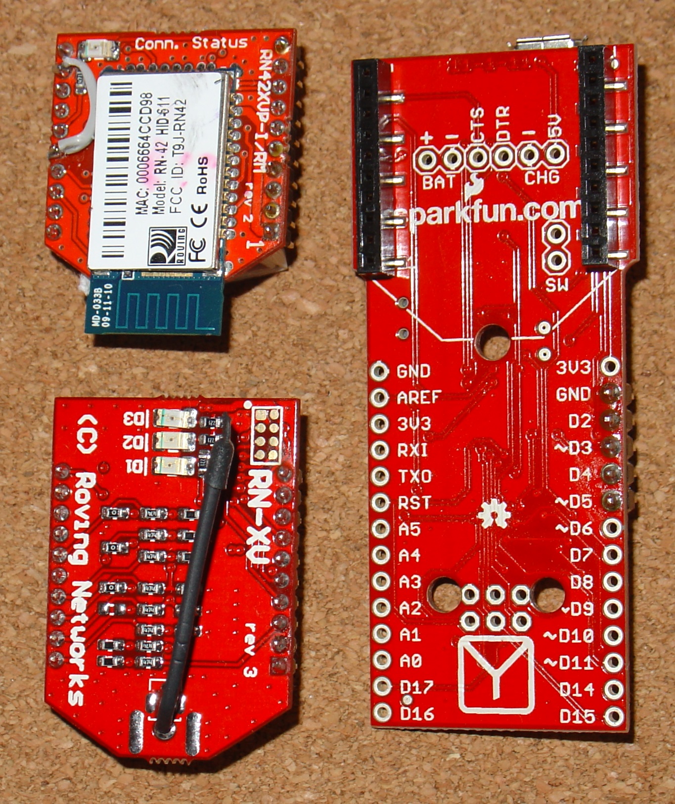
These images show the top and
bottom views of the FioV3 board and the two modules. See below re
wire link on bluetooth module. As well as the FioV3 board and the
module you want to configure you will need a MicroUSB
cable.
The SparkFun FioV3
Arduino board has a number of useful features over and above the
standard UNO arduino board:-
a) XBee connector that will accept,
XBee, bluetooth or wifi daughter boards
b) Lithium-ion battery
connection
c) USB powered lithium-ion battery charger.
d) USB
support, Serial
e) Serial UART (separate from the USB), Serial1.
This simplifies debugging.
f) On board power regulator so the
board can be powered by USB (or higher voltages)
g) 3.3V supply
voltage (uC will operate down to 2.7V)
h) Differential ADC inputs
with gains of 1x, 10x, 40x and 200x
There are a few problems
with this board (as at V3) :-
i) If the battery and USB is
attached and the board switch turned ON then excessive voltage is
applied to the battery which becomes unstable. The in-line PTC
provides protection against high currents but even overcharging at
low currents are dangerous (see below for a fix)
ii) Pin 13 (the
stardard LED pin) is connected directly to the STAT output of the on
board Li-ion battery charger chip. If a battery is connected to the
board and you load a sketch that drives the LED, pin 13, then you may
damage the micro-processor or the battery charger chip or both. Other
Arduino boards have a current limiting resistor between pins that can
both be set as outputs. Fio V3 has no such protection.
iii) The
battery monitor resistors are permanently connected to the battery
even when the board is turned off. This continually drains the
battery if you use the battery powered option.
iv) Not all the
XBee socket pins are accessable via test points.
v) The XBee Pin 1
lable on the FioV3 board is actually next to pin 20 of the XBee
socket.
Point i) Carefully cut
the SJ2 link to disconnect the USB voltage from the RAW lead. The
down side is that the board will not longer be powered from the USB
so you will need to connect a battery.
Point ii) cannot be easily
fixed. DO NOT set pin 13 as an output!!
Point iii) can be 'fixed'
by removing, carefully, resistor R14.
Point iv) will be discussed
below.
Point v) is just confusing.
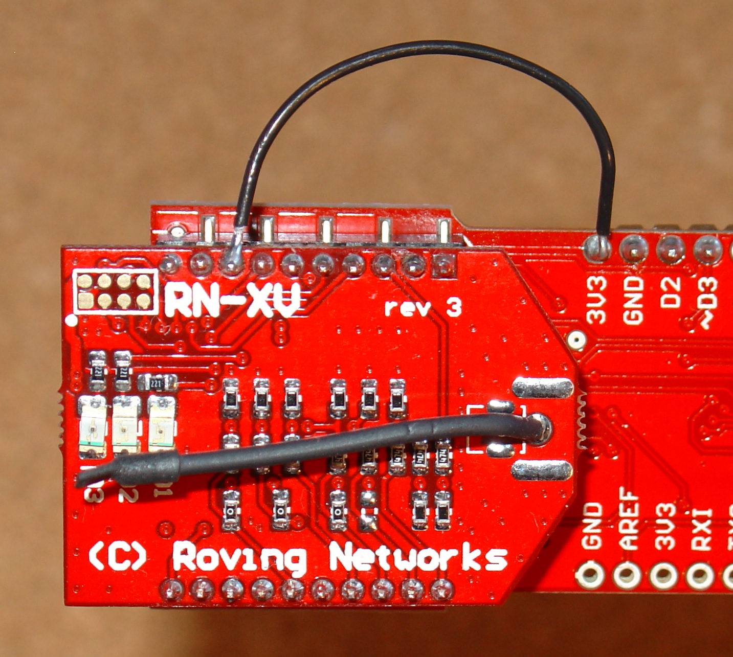
To get this module to work, some soldering is required. The RN-42 module swaps the CTS and RTS pins when compared to the standard XBee board. The FioV3 only provide access to the XBee CTS pin (pin 12) and does not provide a test point for pin 16, the XBee RTS pin.
This is fine for XBee plugins but for the RN-42 bluetooth board, which by default comes with hardware handshaking enabled, it means you will get nothing back as the CTS pin (pin 16 on the RN-42) is not pulled low.
To fix this solder a small wire between pin 12 and pin 16 on the
RN-42 board (see photo below)
(Click
image for a hi-res version)
With this wire in place, CTS will be pulled low by RTS whenever the bluetooth board wants to send data. Once the wire is in place you can plug the RN-42 bluetooth daughter board in, as shown above, and configure it.
To set up the Arduino IDE see arduino.cc/en/main/software. After installing the IDE you need to add the driver and hardware files for FioV3 to your Arduino installation. Download them from the SparkFun's FioV3 page and follow the readme.txt instructions included.
The FioV3 board is very convenient for configuring the daughter boards because the serial UART connected to the XBee socket is separate from the UART interface to the USB port. This means you can use a simple sketch to connect to and configure the daughter board. There are two similar sketches FioV3_2Serial_115200.ino and FioV3_2Serial_9600.ino. You can right click these links and save them to open in the Arduino IDE or just copy and past the text into an empty sketch.
The first one, FioV3_2Serial_115200.ino, works with the bluetooth board in Factory Default 115200 baud rate. The second sketch, FioV3_2Serial_9600.ino, is used once the bluetooth's baud rate has been change to 9600 (see below).
void setup() {
   // Open serial communications and wait for port to open:
   Serial.begin(9600);
   Serial1.begin(115200);
}
void loop() {
   if (Serial1.available())
      Serial.write(Serial1.read());
   if (Serial.available()) {
      byte in = Serial.read();
      Serial.write(in); // local echo
      Serial1.write(in);
   }
}
Checking
the USB drive's baud rate.NOTE:
The
baud rate for the USB driver does not seem to have any relationship
to the FioV3 USB
Serial
baud
rate. However for consistency, in the sketch the UBS serial (Serial)
baud rate is set to 9600, and the Serial Monitor is set to 9600 and
you should check that the USB driver is also set to 9600.
To check
the USB drive baud rate, open the device manager

and then double click the Fio V3 Com port to open its properties and set the baud rate to 9600

Here I am goint to set the RN-42
bluetooth module to 9600 baud, SPP profile, Pin Authenication and the
pin code, and Slave mode.
Check Bluetooth-RN-UM.pdf
and RN-HID-User
Guide-1.1r.pfd for all the options. Check the
www.rovingnetworks.com
for the last versions of these documents.
Load
the sketch
FioV3_2Serial_115200.ino
and
program the FioV3 board.
NOTE:
If
loading the FioV3 fails, check these points.
A) no other program
is connected to the USB COM port, e.g. telnet software or Arduino
Serial Monitor
B) The Arduino IDE can see the COM port. Check the
Tools menu. If the COM port is missing, unplug and plug the FioV3
board back in to fix this and/or close and re-open the IDE.
C)
the correct COM port in the tools menu is ticked. Disable bluetooth
on your PC to remove a lot of other COM ports.
In
order to get the RN-42 into CMD mode, you need to send $$$
but
without any CR/LF.
So
open the FioV3_2Serial_115200.ino sketch, check the baud rate is the
factory default, 115200. Load the sketch into the FioV3 board and
then open the Serial Monitor and set the line ending to
“
No
line ending”
and
type in $$$ and click SEND.

The
bluetooth module should respond with CMD
if
it does not, the default baud rate is too high. Instead is shows
CSTH.
Don't worry about this just continue to enter the commands
as shown below after changing the line endings back to “Both
NL & CR”.
Change
the line endings back to
“Both
NL & CR”
and
enter the following two commands, one at a time,SU,9600
R,1

This
sets the baud rate on the bluetooth module to 9600 and reboots it.
Once
you have done this you can use the sketch, FioV3BluetoothSetup.ino,
to complete the configuration shown below. Copy and past the sketch
into your Arduino IDE. Then upload the sketch to your board and open
the IDE SerialMonitor within 10 secs to observe the results.
Connecting
RN-42 bluetooth via Adruino Serial Monitor and FioV3 (if you want to
do the configuration by hand).NOTE:
Once
you have changed the baud rate from the default 115200 to 9600, you
will need to change the Serial1
baud
rate in the sketch setup() to use 9600 when you try and connect
againSerial1.begin(9600);NOTE
it is the Serial1
(with
a 1 at the end) whose baud rate you need to change.
The
sketch FioV3_2Serial_9600.ino
has
this change made, so after the reboot you can just load that sketch
and reprogram the FioV3 board to do the rest of the configurations.
Now having compile the sketch
(FioV3_2Serial_9600.ino)
and upload it to the FioV3 board and connecting again using the
Serial Monitor, this time when you send $$$ (without any line
endings) you will see CMD. You are in cmd mode. (Note: to exit CMD
mode either reboot using the command R,1
or the command ---,
(i.e. three minus signs) both these commands need “line
endings” of at least CR,
here I use line endings “Both
NL & CR”)

Now you can continue to enter the other configuration commands.
Having changed the baud rate to 9600, here are the other settings I changed. With these changes allow you will be able to connect to the bluetooth module from some other device and send and receive serial data. In my case, I connect from my pfodApp on my Android phone, to the RN-42/FioV3 running as a pfodDevice.
The commands I used to change the settings where:-
SM,0
Slave mode, in this mode other Bluetooth
devices can discover and connect to the device.
SA,4
Authenication, This
mode is PIN code mode, which forces Bluetooth version 2.0 PIN code
authentication. (see RN-HID-User Guide-1.1r.pfd)
SP,0000
Set
the pin code to 0000 (choose some other value here for security)
ST,0
Configuration
timer, ST,0 disables remote configuration and prevents anyone
changing the configuration via the bluetooth connection.
S~,0
Enables SPP protocol (as opposed to HID
profile) SPP allows you to send and receive serial data. (see
RN-HID-User Guide-1.1r.pfd)
SN,IR_TypeK_meter
This set the bluetooth device
name (max 20 chars)
D-
Prints out the main settings for you to check.
R,1
Reboot! To apply these settings. Finished
That's it, finished. You can now connect to the FioV3 via bluetooth and send and receive data via the bluetooth connection using Serial1 in your sketch.
This sketch FioV3wifiSetup.ino does all of the following configuration for you. Copy and past the sketch into your Arduino IDE and edit the ipAddress, localPort, accessPointNetworkName and WPA_key to suit your wifi network. Then upload the sketch to your board and open the IDE SerialMonitor within 10 secs to observe the results.
This module is much easier to get
running. Its factory default is 9600
baud rate, 8 bits, No Parity, 1 stop bit, and hardware flow control
disabled.
So you can just plug it into the FioV3 and upload the
FioV3_2Serial_wifi.ino
sketch,
open the Serial Monitor and send $$$
with
No
line ending
the
RN-XV module responds CMD.
Once
you are in CMD mode, set the line endings back to “
Both
NL & CR”
(Note:
to exit command mode use either the
exit
or
reboot
commands
both these commands need “
line
endings”
of
at least CR, here I use line endings “
Both
NL & CR”)
Note:
the RN-XV wifi module echos back the config commands itself (unlike
the bluetooth module above).
Connecting
via an adhoc Network
Another
alternative is to wire pin 8 on the RN-XV module to 3V3 on FioV3 to
force the wifi module into adhoc mode on power up.
(Click
image for hi rev version)
You
can then connect to the adhoc network via your computer and configure
the wifi module via telnet.
You
need to disconnect your computer from all other networks and then
connect to the RN adhoc network (see see WiFly-RN-UM.pdf
for the details). Once your computer has obtained an ip address on
the adhoc network, this can take a couple of minutes, you can open a
telnet session to 169.254.1.1 port 2000. The RN module should respond
*HELLO*. You can then type
$$$
(no
carrage return!) to enter CMD mode and setup configuration below.
NOTE:
When
using the adhoc mode for setting the config, once you use the
set
ip localport 4989
command
below and save
that
value to config and reboot
you
will need to connect to 169.254.1.1 port
4989
instead
of port 2000
Entering
the RN-XV wifi configuration.You
can then type $$$
(no
carrage return!) to enter CMD mode and setup configuration
below.
NOTE: If you configure the module a second time, *HELLO*
will not be seen on connection, AND you must confiigure the IP number
again before you save the configuration otherwise the default
169.254.1.1 number will be saved.
Then to set the RN-XV wifi module up to allow it to be connected to by some client (i.e. pfodApp), I set these configurations (see WiFly-RN-UM.pdf for the details). You need to know the network name SSID and password for your wifi access point and the type of security it uses. In my case my access point uses WPA2-Personal with AES.
set ip tcp-mode 0x0 – use this one
set ip
tcp-mode 0x10
NOTE: do not use this setting if
you want to use adhoc access for later configuration. This
disables remote configuration so no one can modify the config with
actual physical access to the module.
set comm close 0
This removes the default *CLOS*
message sent on the serial connection when the connection closes. See
below for how to determine the connection status via hardware. Omit
this setting if you want your Arduino program to be notified with at
text msg when the connection closes.
set comm open 0
This removes the default *OPEN*
message sent on the serial connection when a connection is
established. See below for how to determine the connection status via
hardware. Omit this setting if you want your Arduino program to be
notified with at text msg when a connection is established.
set comm remote 0
This removes the default *HELLO*
message sent via wifi to the remote end when a TCP/IP connection is
established. Once you have finished testing you should remove this
message to deny hackers using port scanners any information about
what they have connected to.
set comm match 0
This disables the match char used
to send buffered chars. I tried setting 10 for NL (newline) as the
char to force the sending of buffered characters, Arduino send CR
(\r) and then NL (\n) when println() is called, but found
occasionally I lost some chars (this should not happen). Setting to 0
seems to have solved the problem. Setting to 0 (the default) means
the buffered chars will be sent when there are 1024 chars waiting (at
9600 baud) in the wifi board OR 10mS has elapsed since the last char
have arrived from the arduino board to the wifi's serial connection
via the XBee socket.
set ip address 10.1.1.100
This sets a static ip
address for this module. A static ip makes it easy to connect to.
Choose some free ip address on your network. You should modify your
access point DHCP configuration to exclude this address from the DHCP
range so that this address is not automatically assigned to some
other device. Setting a high number (.100 to .254) here means it is
unlikely to be allocated by DHCP even if you do not modify the DHCP
configuration.
set ip dhcp 0
This disables the DHCP and prevents
the static ip address being overwritten.
set
ip localport 4989
This sets the port the wifi
module listens on for a connection. Choose some number between 1024
and 65000. NOTE: After saving this setting when next you want to
connect via adhoc you need to set you telnet to connect to
169.254.1.1 port 4989 as only the ip is overridded in adhoc
mode. The save port is used as is.
set ip protocol 2
Allow TCP/IP server connections.
Do NOT use “set ip protocol 6” if
you want to reconfigure via adhoc as setting protocol 6
reject packets whose destination ip address does not match the static
address set for this module. In adhoc mode the save ip is replaced
with 169.254.1.1 but it incoming packets are still check against the
saved ip.
The opt password is not set as pfodApp has a much more secure CHAP authentication process which avoids sending the password over the internet.
set sys iofunc 0x40
This enables the hardware
connection indication. GPIO-6, high = connected, low = not connected.
GPIO-6 is connected to the XBee socket pin 15 which on the FioV3
board is connected to ASO led. As described below by wiring the XBee
socket pin 15 to a spare digital input your sketch can determine when
the wifi module is connected/disconnected.
set sys printlvl 0
Suppress all the status
messages.
set wlan auth 4
Set the security setting, in my
case WPA2-PSK.
set wlan join 1
Only join the access point that
matches the stored SSID and passkey
set wlan phrase your_WPA_key
Set
the secret WPA key. See WiFly-RN-UM.pdf
if the key has spaces in it.
set wlan rate 0
Increases the effect range.
set wlan ssid
assess_point_network_name
Set the SSID name of your access point
here. See WiFly-RN-UM.pdf
if the key has spaces in it.
Finally use the save command to save these
settings
save
Saves the settings.
get everything
displays all the settings for
checking
reboot
reboots the module using the saved
settings.
That's if finished. Remove the adhoc wire if you added one (or insert a switch so you can easily switch back to adhoc mode config). On power cycling the RN-XV module should automatically connect to your access point (provide it is in range) and you should be able to connect to it using the ip and port number you set in the config above.
The General Purpose Android/Arduino Control App.
pfodDevice™ and pfodApp™ are trade marks of Forward Computing and Control Pty. Ltd.

Contact Forward Computing and Control by
©Copyright 1996-2020 Forward Computing and Control Pty. Ltd.
ACN 003 669 994