
|
Home
| pfodApps/pfodDevices
| WebStringTemplates
| Java/J2EE
| Unix
| Torches
| Superannuation
|
| About
Us
|
|
|
Cheap NMEA/AIS Hub
|
by Matthew Ford 11th Jan 2022 (originally posted 6th
September 2020)
© Forward Computing and Control Pty. Ltd.
NSW Australia
All rights reserved.


Update 11th Jan 2022 – Added
DHCP and note about static IP's in Help - No
Data
Update 9th August 2021
– Fixed links to
pfodESP8266BufferedClient library
Update 9th January
2021 – Added extra TCP
connection and reuse last connection if more clients connect
Update
13th December 2020 – Added no
config version of the code.
This NMEA / AIS RS232 to WiFi bridge is based on the ESP8266-01 WiFi Shield. AIS is automatic identification system to show the position of nearby ships. NMEA 0183 is the National Marine Electronics Association standard used for GPS messages.
The RS232 to WiFi bridge has been modified from the ESP8266-01 WiFi Shield to be powered by a 12V battery and accept an RS232 input (+/-15V) and create a local network which broadcasts the data via TCP and UDP. It was developed in conjunction with Jo who wanted to run a cheap and simple self contained local network to access his AIS's data from anywhere on his yacht. This resulting module creates an Access Point (a Router) and sets up a TCP server for up to 4 connections and also broadcasts the data on a UDP broadcast group. A configuration webpage is provide to set the TCP and UDP port numbers, the WiFi Tx power and the incoming RS232 baud rate. Unlike the WiFi Shield, there is no configuration button, so once constructed the module can be completely sealed water tight. Protection circuits are include to make this device robust against miss-wiring. While designed with NMEA (GPS) and AIS in mind, the module will handle any RS232 data with baud rates between 4800 and 38400 (and others by editing the Arduino sketch).
Uses the inexpensive and readily available
ESP8266-01 module :- Other ESP8266
modules can also be used
Robust :-
The
circuit has a number of protections built in to guard against
mistakes when wiring up.
Power
Efficient :- A
DC-DC converter power supply efficiently powers the unit from a 12V
battery and the WiFi Tx power can be reduced to save more
power.
Simple
to use :- Just connect a 5.5V to 12V
supply and the RS232 TX line and then join your reciever to the
network and connect to the TCP or UDP service to receive the data.
Can be quickly swapped for a spare one if the unit fails
Simple
to configure :- There is no
re-programming necessary, no special configuration mode. A
configuration page is provided which allows you to set the RS232
baud rate and the WiFi transmit power and the port numbers for the
TCP and UDP servers
Optional No
config version :- There is also
another sketch where all the config is pre-programmed. This is for
those situations that already have a local network running with its
own router (Access Point)
This ESP8266-01 RS232 to WiFi Bridge needs the following parts, or similar. The prices shown here are as at August 2020 and exclude shipping costs and some sort of plastic case :-
WiFi Module ESP8266-01 – ~US$1.50 online
(take your chances)
OR for reliable product SparkFun
ESP8266-01 – US$6.95
MPM3610 3.3V Buck Converter Adafruit
– US$5.95 5V to 21V input, OR DC-DC 3A Buck Step-down Power
Supply Module online Aliexpress ~US2.00
10-pin header Element14
– US$0.40 (or 28
Pin Header Terminal Strip from Jaycar AU$0.95)
1 off 1N5711
Schottky Diode Digikey
US$1.15 (or Jaycar
AU$1.60)
2 off 1N4001 Diodes SparkFun
US$0.30 (or 1N4004 Jaycar
AU$1.00) Any 1A 50V or higher diode will do, eg
1N4001,1N4002,1N4003,1N4004
1 off 2N3904 NPN transistor SparkFun
US$0.50 (or Jaycar
AU$0.75 any general purpose NPN with Vce > 40V, Hfe > 50 at
1mA, Ic > 50mA e.g. BC546, BC547, BC548, BC549, BC550, 2N2222
6
x 3K3 resistors e.g. 3K3
resistors – Digikey – US$0.60 (or 3K3ohm
1/2 Watt 1% Metal Film Resistors – Pk.8 from Jaycar
AU$0.85)
3 off 330R resistor Element14
US$0.10 (or 330ohm
1/2 Watt 1% Metal Film Resistors – Pk.8 from Jaycar
AU$0.85)
1 off 10K resistor Element14
US$0.05 (or 10k
Ohm 0.5 Watt Metal Film Resistors - Pack of 8 from Jaycar
AU$0.85)
Vero board (links and bus rails) Jaycar
HP9556 OR (strip copper) (strip copper) e.g. Jaycar
HP9540 ~AU$5.50
and a plastic case and hookup wire.
Total Cost ~US$9.90 + shipping and plastic case (as of August 2020) using Aliexpress ESP8266-01 and DC-DC module OR ~US$19.30 using Sparkfun ESP8266-01 module and Adafruit DC-DC buck converter. Cheap enough to make a couple of spares.
To program the RS232 to WiFi Bridge, you also
need a USB to Serial cable. Here a SparkFun's USB
to TTL Serial Cable (US$10.95) is used because it has nicely
labelled ends and has driver support for wide range of OS's
Including
the programming cable, the cost for just one RS232 to WiFi Bridge is
~US$20 to US$24 (plus shipping and a case).
Above is the circuit diagram for the RS232 to WiFi Bridge (pdf version). This has been adapted from the ESP8266-01 Wifi Shield and modified to accept RS232 and a 5V to 12V (battery) supply. The DC to DC converter provides power efficient operation from a 12V battery for night time use when there is no solar power and power usage is at a premium.
A number of circuit protections have been built into the circuit. The connections on the left hand side of the circuit are only used during construction to program/debug the unit. The 330R resistors R6 and R7 protect against shorting a TX output to a TX output when programming/debugging. When programming you connect TX to RX and RX to TX. The debug TX output should be connected to an RX UART 3v3 input to see the debug output (see the comments in the ESP8266_NMEA_BRIDGE.ino sketch).
The connections on the right hand side of the circuit are used to connect the completed unit to the power supply and the NMEA/AIS RS232 source. These are the only connections that need to be accessible once the unit is built. Keep these connections in pairs.
The 2N3904 provide the inversion and level shifting from the RS232 +/-15V signal to the TTL UART input to the ESP2866. The reverse voltage between the Emitter and Base of the 2N3904 is specified to withstand at least 6V. The D4 limits the reverse Emitter Base voltage to be less than 1V when the the RS232 input is -15V.
Finally, “RS-232 drivers and receivers must be able to withstand indefinite short circuit to ground” (RS232 wikipedia) so if you accidentally connect the RS232 lines to the Power Supply terminals, it should not damage the NMEA/AIS device.
The diode D1 prevents reverse voltage being applied to the DC-DC converter if you happen to swap the +V and GND connections when wiring up. D1 has a small leakage current. D2 provides a low voltage path for that leakage current to keep the reverse voltage on the DC-DC converter below -0.3V. The 330R resistor (R10) in the RS232 GND line provides protection against shorting the battery to ground if the battery +ve lead is connected to the board's Power Supply GND wire while the RS232 GND is connected.
The DC-DC converter is rated for up to 21V operational input so it is suitable for a 12V battery while it is being rechanged. A battery on full charge can be up to ~14.8V and the charger voltage can be higher, 16V or more. The 21V input rating of the DC-DC converter is rated to handle this. Accidental reverse supply connection (in the middle of the night in rough weather) is protected against. The absolute maximum voltage for the converter input is 28V an so can handle have an RS232 signal connected to it. RS232 voltage is specified to be less than +/- 25V.
If you accidentally connect the leads from your power supply to the RS232 TX/GND connections (either swapped or not), the 10K and the 330R resistors will protect against shorting out the power supply.
In summary the circuit is protected against swapping power and RS232 leads and connecting the wires from those pairs in either way around. Mixing up wires, one from each pair, is not protected against in all combinations so keep the RS232 and power leads paired and connect them in pairs.
The average current used by the board is about 100mA (depending on the WiFi transmit power and data rate). If a simple linear regulator was used to power the board from a 12V battery the power usage would be 12V x 100mA = 1.2W or 1.2Ahrs over a 12 night. Using the DC to DC converter, which ~70% efficient, reduces this load to 0.47W or 0.47Ahrs over a 12hr night.
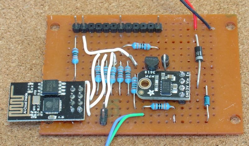
I constructed this unit using a small piece of vero board with links and power buses. Here are the top and bottom views of the completed board. Make sure you carefully check the wiring when you are finished. It is easy to wire to the wrong pin when you turn over and wire from the bottom.

Each RS232 to WiFi bridge needs to be programmed once, only, and never again. A built-in webpage provides access to the available configurations.
To program the shield follow the instructions given on https://github.com/esp8266/Arduino under Installing With Boards Manager. When opening the Boards Manager from the Tools → Board menu and select Type Contributed and install the esp8266 platform. This project was compiled using the ESP8266 version 2.6.3. Later versions may be better but may have their own bugs as the platform is evolving rapidly.
Close and re-open the Arduino IDE and you can now select “Generic ESP8266 Module” from Tools → Board menu.
You also need to install, from https://www.forward.com.au/pfod/pfodParserLibraries/index.html, the latest versions of pfodESP8266BufferedClient library (for pfodESP8266Utils.h and pfodESP8266BufferedClient.h) and millisDelay library (for millisDelay.h).
Download
these zip files to your computer, move it to your desktop or some
other folder you can easily find and then use Arduino IDE menu option
Sketch
→
Import
Library →
Add
Library to
install them.
You also need to install the SafeString library. The
SafeString library is available from the Arduino library manager or
you can download the SafeString.zip
file directly for manual installing via Sketch
→
Import
Library →
Add
Library
Stop and restart the Arduino IDE and under File->Examples you should now see pfodESP8266BufferedClient and SafeString.
To program the board, set the board into programming mode by shorting the link (bottom left). Then connect the USB to TTL UART serial cable Note carefully only connect 3V3 TX/RX leads to the left hand side connection using the 3V3 TX/RX from Sparkfun's USB to TTL Serial Cable The cable connections are RX (Yellow), TX (Orange), VCC (5V) (Red), and GND (Black). Note the Yellow (RX) cable is connected to the TX pin on the board and the Orange (TX) cable is connected to RX pin on the board. The Black (GND) cable is connected to the GND for TX/RX pin. Note: There seem to be two versions of this cable. Older versions have 5V Vcc and RX (Brown), TX (Tan-like/Peach), VCC (Red), and GND (Black), in any case the VCC lead is not used here. There are also comments that the TX and RX wire are reversed in some cases. If the Arduino IDE cannot program the board, try swapping the TX/RX cables. The 330R protects against TX-TX shorts.

Power the board from a 6V to 12V 500mA or larger supply or battery. Connect the Power supply -Ve (GND) lead first so that the power supply current does not try to flow back through the USB connection. Preferably use an isolated (floating) 6V to 12V supply or battery. Note the Aliexpress DC-DC modules need at least a 6.5V supply.
Then plug in the USB cable to your computer. Select its COM port in the Tools → Port menu. Leave the CPU Frequency, Flash Size and Upload Speed at their default settings.
Check the photo and your wiring. Also see ESP8266 Programming Tips (espcomm failed)
Compile the ESP8266_NMEA_BRIDGE.ino sketch. Then select File → Upload or use the Right Arrow button to compile and upload the program. Two files are uploaded. If you get an error message uploading check your cable connections are plugged in the correct pins and try again.
Once the programming is completed, remove the programming mode shorting the link and the programming TX/RX connections and then turn the power supply off and on to restart the board in its normal mode.
Connect
the NMEA/AIS device. NOTE: This ESP8266 Access Point does NOT provide
an DHCP service so you need to set a static IP in your receiving
device (iPad/computer, etc).
Because the ESP8266_NMEA_BRIDGE.ino
sets up a network starting at 10.1.1.1, the static IP you set needs
to be on the range 10.1.1.2 to 10.1.1.254. Each device needs its own
unique IP
There is another version of this sketch, ESP8266_NMEA_BRIDGE_noCfg.ino, in which all the configuration is pre-programmed in the sketch code. In this case the NMEA hub connects to an existing router (access point) to make the data available to the network.
The
configuration is all at the top of the ESP8266_NMEA_BRIDGE_noCfg.ino
file.
Usually your router will support DHCP and automatically
allocate IP to your other devices. You must make sure the
ESP8266_NMEA_BRIDGE_noCfg IPAddress staticIP setting does not
duplicate an existing IP on your network. Setting an IP in the upper
range x.x.x.200 to x.x.x.254 will usually be safe.
// =================  HARD CODED CONFIG ==================
const char ssid[] = "yourRouterSSID";   // set your network's SSID here
const char password[] = "yourRouterPassword";  // set your network's password here
IPAddress staticIP(10, 1, 1, 190); // set NMEA hub static IP here. NOTE the , between the numbers
// make sure no other device is running with this same IP and that the IP is in your router IP range
// common router IP ranges are 10.1.1.2 to 10.1.1.254
//  192.168.1.2 to 192.168.254.254 and
//  172.16.1.2 to 172.31.254.254
// the router is usually 10.1.1.1 or 192.168.1.1 or 172.16.1.1 depending on its range
IPAddress udpBroadcaseIP(230, 1, 1, 1);  // set the UDP broadcast IP here. NOTE the , between the numbers. This IP is independent of the router range do not change
const uint16_t tcpPortNo = 10110;  // set NMEA tcp server port No here
const uint16_t udpPortNo = 10110;  // set NMEA UDP broadcast port No here
const unsigned int txPower = 10; // TX power in range 0 to 82;
const unsigned int GPS_BAUD_RATE = 4800;  // the Serial baud rate of you GPS module
// ================= END OF HARD CODED CONFIG ==============
My sailing consultant on this project, Jo, suggested mounting a Red Power led and a Green Data led on the case to indicate that things are running. Here is the modified circuit with these two leds added.
R9
and R11 set the Led current and hence the brightness. Use the largest
resistor that makes the leds still visible. They will be difficult to
see in direct sunlight or in a bright cabin, so mount the unit in a
dark corner for maximum visibility.
Jaycar has suitable bezel leds
Red
and Green
(~AU$2.75) and Sparkfun has some super bright Red
and Green
leds (US$1.70) but almost any red and green led will do.
When you power up the board after programming, it will automatically create a local network. That is it will become a local Access Point (router). The network name will start with NMEA_ followed by 12 hex digits unique to each board, eg. NMEA_18FE34A00239 The password for the local network is always NMEA_WiFi_Bridge. If you need to swap units at sea, power down the old one, install the spare and then look for the new NMEA_..... network and use the password NMEA_WiFi_Bridge to join it.
If you cannot see the network, move closer to the circuit board and check that you have the power cables connected correctly. There should be a blue light one the ESP8266-01 board.
Once you have joined the network with your computer, or mobile phone, you can open the configuration webpage at http://10.1.1.1 (Note: type in http://10.1.1.1, if you just type in 10.1.1.1 you may get Google trying to search for it and failing since you are not connected to the internet). If the page is not found, check that you have set a static IP on your computer/mobile in the range 10.1.1.2 to 10.1.1.254.
This page lets you set the WiFi transmit power. Lower numbers for less power and range and current consumption. You can also change the port numbers for the TCP and UDP connections. The default 10110 is the designated port for NMEA connections, but you can choose your own if you wish. The IP numbers are fixed. Finally you can set the baud rate to match your NMEA/AIS source. 4800 baud is the standard baud rate for NMEA. While 34800 baud is the standard baud rate for AIS.
Once you have made your selections, click Submit and a summary page of the changes that have been stored is shown.

If these are not correct then use the browser back button to go back and fix them. To apply the changes the board needs to be restarted. Clicking the Apply these change button will do that.

Once the board restarts it will automatically show the configuration page again with the current configuration.
Connect your
computer or mobile device to either the TCP or UDP connection and
check you are getting data.
That's
it finished!! Seal every thing up in a water tight plastic box
leaving only the two power leads and the two RS232 leads free.
Once you have connected to the network and set your mobile device to connect to the TCP 10.1.1.1 and the port you have set (or join the UDP multicast group 230.1.1.1 with the port you have set), if you still do not get any data try the following steps.
1) Check the NMEA / AIS equipment is turned on
2)
Check the RS232 cables are connected the right way around.
3)
Check the 'flow control' setting on your NMEA / AIS equipment. Set it
to 'NONE' if that is an option. If not then choose 'hardware' OR
RTS/CTS flow control and short out the RTS to CTS and DSR pins of the
NMEA / AIS cable. That is for a DB-25 connector, connect pins 4 and 5
and 6 together. For a DB-9 connector, connect pins 6 and 7 and 8
together. With 'hardware' control the NMEA / AIS equipment (the DTE)
asserts RTS (ReadyToSend) when it wants to send data. With these
connections the RTS pin drives the ClearToSend (CTS) and DataSetReady
(DSR) pins which are input back into the NMEA / AIS equipment to tell
it that the other side is ready and able to receive data.
4) By
default the Bridge supplies an IP to your device via DHCP in the
range 10.1.1.100 to 10.1.1.200. However if you cannot connect to the
config webpage on 10.1.1.1 or cannot receive any data, you may need
to manually set an IP in the range 10.1.1.2 to 10.1.1.99 on your
computer/device. Also check if you have a manual static IP set for
some other network range and if so change to a static IP in the range
10.1.1.2 to 10.1.1.99
To turn on the Debugging TX output, uncommenting, i.e. edit
to
#define DEBUG
near the top of the
ESP8266_NMEA_BRIDGE.ino
sketch.
Remove the TX/RX USB cables and just connect the Yellow RX cable to the Debug TX output. Leave the Black GND cable connected to GND for TX/RX. The Arduino IDE Serial Monitor will now show debug messages.
By
default the UDP multicast group is started, but you can disable it by
commenting out, i.e. edit to
//
#define UDP_BROADCAST
near
the top of the
ESP8266_NMEA_BRIDGE.ino
sketch.
This NMEA/AIS RS232 to WiFi bridge is robust and simple to use. It efficiently runs from a 12 battery source and is cheap enough to carry a spare with you that you can swap in mid voyage if necessary.
AndroidTM is a trademark of Google Inc. For use of the Arduino name see http://arduino.cc/en/Main/FAQ
The General Purpose Android/Arduino Control App.
pfodDevice™ and pfodApp™ are trade marks of Forward Computing and Control Pty. Ltd.

Contact Forward Computing and Control by
©Copyright 1996-2020 Forward Computing and Control Pty. Ltd.
ACN 003 669 994


