
|
Home
| pfodApps/pfodDevices
| WebStringTemplates
| Java/J2EE
| Unix
| Torches
| Superannuation
|
| About
Us
|
|
|
ESP-01 and ESP-01S
|
by Matthew Ford 2nd Jan 2022 (originally posted 28th
July 2015)
© Forward Computing and Control Pty. Ltd. NSW
Australia
All rights reserved.

Programming the ESP-01 and ESP-01S
Using
the ESP-01S and ESP-01 Leds
Setting
the LED_BUILTIN value
Using TX/RX as
normal GPIO pins
Debugging
while using RX as normal GPIO pin
Best
Pin Trick – Use I2C
Using the GPIO0
/GPIO2 for OUTPUT and RX for INPUT
How
to reprogram when using GPIO0 as an output
Another
Trick – Driving a Relay and Reading a Push Button using GPIO0 /
GPIO2
How to Avoid Relay
Flicker on Startup
Detecting
WiFi Config Mode via Pin Input
Detecting
WiFi Config Mode via Software
Detecting
the Manual Override Push Button
ESP8266-01 is a very low cost WiFi enabled chip. But it has very limited I/O. At first glance, once you configure it for programming, all the pins have been used. This page builds on Using ESP8266 GPIO0/GPIO2/GPIO15 pins to show you how you can get four (4) usable inputs/outputs for you next ESP-01/ESP-01S project and how to use IC2 to get even more inputs. It also covers how to drive the on-board Blue Led and has links to how to program the ESP-01.
The code here assumes you are programming the module using the Arduino IDE setup as described on https://github.com/esp8266/arduino under Installing With Boards Manager. When opening the Boards Manager from the Tools → Board menu and select Type Contributed and install the esp8266 platform. Also see ESP8266 Programming Tips (espcomm failed)
Both these boards are programmed using the Generic ESP8266 board setting.
Before you think about programming, think about
how you will use the programmed module. The ESP-01(S) needs a 3V3
supply with >250mA capacity and extra external resistors. There
are two basic options which give you programming and debugging
capabilities :-
1) you are building your own breadboard with a
power supply and resistors such as shown in these projects ESP8266-01
Wifi Shield and Cheap
NMEA/AIS Hub. In those cases you should use a USB to 3V3 TTL
convertor such as USB
to TTL 3V3 Serial Cable or similar.
2) you are using a
pre-built module, such a the ESP-01 Relay module used in this project
ESP-01
Power Timer. In those cases you should use a ESP-01 serial
adaptor with breakout pins, ESP
Link V1.0. Make sure you get the one with the extra pins on the
end.
See the above projects for how to program the ESP-01 using these hardware options. Instead of a USB to TTL 3V3 Serial Cable, it is also possible to program the ESP-01 using an Arduino UNO, using this circuit, but don't use the UNO 3V3 power pin as the ESP-01's power supply it is only rated at 150mA and can cause problems when trying to debug a project that uses WiFi.


The
ESP-01 and ESP-01S are the smallest ESP8266 modules and only have 8
pins. Of these VCC, GND, RST (reset) and CH_PD (chip select) are not
I/O pins but are needed the operation of the module. This leaves
GPIO0, GPIO2, TX and RX available as possible I/O pins, but even
these have pre-assigned functions. The GPIO0 and GPIO2 determine what
mode the module starts up in and the TX/RX pins are used to program
the module and for Serial I/O, commonly used for debugging.
GPIO0 and GPIO2 need to have pull-up resistors connected to ensure the module starts up correctly. The ESP-01S has 12K resistors on the board for GPIO0, RST and CH_PD (see the schematic above and also here, local copy here)

The ESP-01S only has one led, a Blue led connected to GPIO2. It turns on when GPIO2 is output LOW. It is simple to use just drive GPIO2 as you need to the turn the led on and off. Here is a simple sketch, ESP-01S_LedFlasher.ino, using the PinFlasher class to flash the Blue Led on an ESP-01S.
For the ESP-01 things are a bit more difficult. There is a Red led that comes on when the 3v3/GND is applied. If you see a Red led, you have an ESP-01. The Blue led on the ESP-01 is driven by the TX (GPIO1) pin and normally just flickers when your are sending data on the Serial connection. However if you are not sending any Serial (debug) data, you can also just drive the GPIO1 pin to drive the led as normal. Here is another simple sketch, ESP-01_LedFlasher.ino, for driving the ESP-01 Blue led. It has two options. If you uncomment the #define DEBUG at the top then Serial is started and the Blue led does not flash but only flickers as debug msgs are sent. If the #define DEBUG is commented out then the Blue led flashes at one second intervals.
Recent version of Arduino IDE have a pre-defined LED_BUILDIN defined that can be used as the pin that is connected that boards led. This presents a problem for the ESP-01 and ESP-01S which are both programmed using the Generic ESP8266 setting but which have different pins for the onboard led. Under the tools menu for the ESP8266 V3.0.2+, under the Board setting there is the Builtin Led setting. This only changes the value which the LED_BUILTIN will return. If your sketch uses LED_BUILTIN then select Builtin Led:1 for the ESP-01 and Builtin Led:2 for the ESP-01S.
As the sketch above shows, you don't need to do this just to drive
the Blue led on an ESP-01. However if you are using GPIO1 (TX) to
drive the led then that leaves GPIO3 (RX) available as a normal
I/O.
If your circuit uses TX (GPIO1) as an output and RX (GPIO3)
as an input then all you need to do is not call Serial.begin( ) as
this is the default setting for GPIO3.
If you need to use GPIO1 as an input or GPIO3 as an output, then
you only need to call the appropriate pinMode( ) either INPUT,
INPUT_PULLUP or OUTPUT. This example sketch, ESP-01S_tx_input.ino,
uses pinMode(1,INPUT) to turn the Blue led on/off via GPIO2.
Remember the ESP8266 ALWAYS outputs a start up message on
GPIO1, so for that short time GPIO1 is ALWAYS an output. So be sure
to add a series 330R resistor between GPIO1 and whatever output is
driving that input to prevent shorting things out during the startup
message.
Setting GPIO3 (RX) as an OUTPUT is NOT recommended if you
can avoid it because
it is easy to short out when next re-programming.
Note
carefully: If you are using GPIO3 (RX) as an output, add a small
resistor say 330R in series to prevent accidentally shorting it out
when you attach your programming leads.
Once
you start using GPIO1 (TX) and GPIO3 (RX) as normal I/O, don't call
Serial.begin(115200) as it will confuse things (but see next for
alternatives). So cannot debug using the Serial connection. However
you can still debug via GPIO2 (TX only) by starting Serial1
instead of Serial. See
this project for an example of sending debug to GPIO2.
To keep the debugging simple, you can
also choose to keep using TX as the standard debug output while
freeing up RX (GPIO3) as an input by using
the Serial.begin( )
statement
Serial.begin(115200,SERIAL_8N1,SERIAL_TX_ONLY);
This
allows you to use RX as normal I/O, while still writing debug
messages to Serial.
Or
Serial.begin(115200,SERIAL_8N1,SERIAL_RX_ONLY);
which
allows you to receive Serial input but not send output, but leaves
GPIO1 available for general I/O use.
Again add a 330 ohm resistor between the RX lead to the Flash programmer TX connection to protect against shorting out the programmer's or the ESPs pin if it connected while RX is an output.
The best trick to get extra inputs into the ESP8266-01 is to use an I2C interface.
One choice is to use GPIO0 and GPIO2 as the I2C bus.
The pullup resistors needed to get the module to start up correctly can double as the I2C bus pull-up resistors and the other, slave, components on the bus are open collector and so should not pull the bus down on power-up. However in some cases slaves, particularly those with battery backup, can become stuck and hold the bus down. In those cases you will need to isolate the bus until the ESP8266 gets through its boot stage.
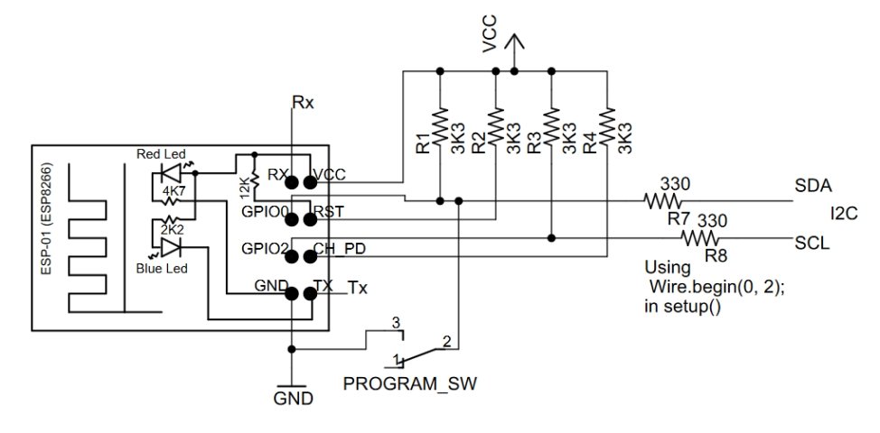
You can avoid this issue by using TX and RX for the I2C bus

A
few things to note:
GPIO1 (TX) is used as the Data line, because you will always get some debug output on GPIO1 on power up. There is no way to suppress this output, but the Clock line (RX) will be held high so none of this data will be clocked to the slaves
When programming the ESP8266, the RX line is connected to the programmer's output. At the end of the programming the ESP8266 reboots and 330 Protection resistor prevents RX shorting the programmer's output drive.
The I2C series resistors provide similar protection for the TX, RX from shorts on the I2C bus
The ESP8266 is 3.3V device so preferably use 3.3V I2C slaves. Many, but not all, I2C devices are are 3.3V these days. “In general, in a system where one device is at a higher voltage than another, it may be possible to connect the two devices via I2C without any level shifting circuitry in between them. The trick is to connect the pull-up resistors to the lower of the two voltages.” (SparkFun I2C tutorial) For a mixture of 5V and 3.3V devices connect the pullup resistors to the 3.3V line, as shown above.
Using I2C is a great way to add a multi-channel A-to-D converter to the ESP8266-01 which does not expose the single ADC input of the underlying module. For example using Adafruit 12bit I2C 4 channel ADC or for analog output SparkFun's I2C DAC Breakout – MCP4725 board. Many other types of sensors are also available with I2C buses.
See http://www.i2c-bus.org/i2c-primer/common-problems/ for more information of overcoming I2C problems. Also see Reliable Startup for I2C Battery Backed RTC for a short method to help clear the bus
While can send debug messages over the WiFi connection it is often convenient to use the TX connection. The next example show how to use GPIO0 and GPIO2 as outputs and RX as an input.

Using
Serial.begin(115200,SERIAL_8N1,SERIAL_TX_ONLY);
allows
you to use RX as a general purpose input (or another output), while
still writing debug messages to Serial. Again the 330 ohm resistor in
the RX lead to the Flash programmer protects against shorting out the
programmer's driver.
NOTE: S1 will have to be open in order to program the ESP8266.
The TX pin accessed from the sketch as GPIO1 and RX is GPIO3
Note:
GPIO0 is needs to be grounded to get into programming mode. If you
sketch is driving it high, grounding it can damage you ESP8266
chip.
The safe way to reprogram the ESP8266 when your code drives
the GPIO0 output is to :-
a) Power down the board
b) short
GPIO0 to gnd
c) power up the board which goes into program mode
due to the short on GPIO0
d) remove the short from GPIO0 so you
don't short out the output when the program runs
e) reprogram the
board
f) power cycle the board if necessary.
Here is another way of configuring the pins. Note: This trick only works if you have a relay module with an isolated input (N1 and N1-com). Because of this limitation and the complexity of the supporting code, the previous example, using RX as an input, is preferable.
Using ESP8266 GPIO0/GPIO2/GPIO15 pins has already covered how to use GPIO0/GPIO2 together to get an extra input. Here that example will be extended to use GPIO0 as an relay driver output and GPIO0/GPIO2 as an input without using RX or TX.
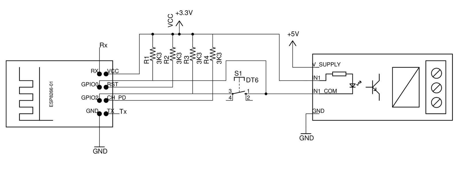
Here is the schematic as pdf
Here GPIO0 is used as an output to drive the relay and GPIO0/GPIO2 is used as an input to read the momentary push button which is used as a manual override to turn the relay on and off, in addition to the remote control over the WiFi connection. The momentary push button is also used to enable the config mode if it is press when power is applied.
The trick here is to do all this while still keeping GPIO0 and GPIO2 high when the ESP8266 module is initializing.
The pull-up resistors, R1 and R3, provide the necessary High for these two pins, but you have to ensure that any extra circuitry attached to GPIO0 and GPIO2 cannot not pull pins low. The optically isolated relay is connected between +3.3V and GPIO0. This keeps GPIO0 high on start up but allows GPIO0 to be made an output, after startup, and ground the relay input to operate the relay. It does not matter if the momentary push button is operated while the module is initializing, as that just connects GPIO0 to GPIO2 and connect both of these to their pullup resistors.
Update 24th Dec 2021 – When the ESP8266 powers up/resets in normal mode, the GPIO0 goes LOW for about 100mS. This will briefly turn ON the relay connected to GPIO0, shown below. To avoid this relay flicker on startup, solder a 470uF to 1000uF 6.3V or higher capacitor across the opto-isolator input pins (after the on-board resistor) on the relay board itself. Check with a multi-meter to get the polarity of the capacitor around the correct way. This capacitor will delay the relay switch by about 0.5sec to 1sec. You could try a capacitor as low as 220uF. The 1000uF one has been tested and works.

Here is the schematic as a pdf.

Using the ESP8266 as a temporary access point you can configure it via a web page as described here. You can use a push button, or shorting link, on power-up to indicate to the software that you want to enter config mode.
Once the ESP8266 module has initialized, it runs the setup() code. In that code, to detect if the momentary push button is pressed, you need not make GPIO0 low to supply a GND to push button and then check the GPIO2 input to see if it low. A side affect of this check is that the relay will always be operated when the unit is being put into config mode. Once you see the relay operate you can can release the push button, because its input will have been detected by then.
Here is some sample code to do this in the setup()
boolean configMode = false; // not in config mode normallyvoid setup() {pinMode(0, OUTPUT);digitalWrite(0, LOW); // make GPIO0 output low// check GPIO2 input to see if push button pressed connecting it to GPIO0configMode = (digitalRead(2) == LOW);if (configMode) {// start AP and get ready to serve config web page// leave relay on to indicate in config mode//......} else {// normal usage// make GPIO0 HIGH to turn off the relaydigitalWrite(0, HIGH);//.....}// rest of setup()}
As an alternative to using a push button, or shorting link, to start up a temporary access point, you can do it in software. This project, ESP-01 Power Timer, includes wifiConfig.cpp / .h files. The wifiConfig.cpp provides two options for turning on a temporary access point to configure the ESP8266 for your network's SSID and password. (The LittleFSsupport.cpp / .h files are also needed as they are used to handle the FS file system)
With
// #define DOUBLE_REBOOT_CONFIG_SETUP
commented out,
the first call to initializeWifiConfig() reads the existing
wifi config from a flash file, or sets the hard coded default values
and returns a pointer to the result. In the main loop,
ESP8266_power_timer.ino, these are used to try and connect to your
network. If it cannot connect, after 30 seconds,
initializeWifiConfig() is called again. This second call
switches on the temporary access point so you can connect directly to
the ESP8266 and open a browser at 10.1.1.1 to set your network's SSID
and password. The name of the closest WiFi network is automatically
filled in, but you can edit it if you need to.

With
#define
DOUBLE_REBOOT_CONFIG_SETUP
un-commented, wifiConfig.cpp implements a much simplified version
of Khoi Hoang's ESP_DoubleResetDetector.
(Stephen
Denne has also has a simple double reboot detector that uses RTC
memory instead of a file)
In this mode a temporary access point will be created if you power-up/reset the ESP8266 and turn it off and on again quickly. This code uses within 10 secs as definition of quickly.
In both cases, the loop() code needs to call
  if (handleWifiConfig()) {
    return;
  }
near the top of the loop() to handle the wifiConfig updates and skip the rest of the loop if you are in config mode.
Finally a QR code is provided to simplify connecting to this temporary access point. See ESP-01 Power Timer for how to create your own code.

The previous section covered detecting when the push button was pressed on power up to enable config mode. We also want to use that push button as a manual override for turning the relay on and off in addition to being able to control the relay via the WiFi link.
The WiFi control of the relay is not covered here, but can easily be done using pfodApp or a webpage. See OLIMEX Menu Generator for how to generate Arduino code with pfodDesigner for ESP8266 modules, or ESP-01 Power Timer for a web page example.
This section will deal with how to detect when the push button is pushed, indicating the user wants to toggle the relay, i.e. turn it OFF is it on or turn it ON if it is off.
The
schematic is the same as above, all the tricks are in the code. There
are two case to consider:-
i)The relay is OFF and the user wants
to turn it on using the push button,
ii) The relay is ON and the
user wants to turn it off using the push button.
In this case the output of GPIO0 is HIGH. Actually GPIO0 can be an input in this case as the pull up resistor R1 will ensure the relay does not turn on. That is the trick. In this case make GPIO0 an Input and make GPIO2 Output LOW and then when the user presses the push button, two things will happen:- a) the relay will turn on due to the ground provided by GPIO2 via the push button and b) the Input GPIO0 will go low. The code checks the state of the Input GPIO0 and when it goes LOW the code knows the use has pressed the push button and wants the relay to be on. The code then makes GPIO0 an Output LOW to keep the relay on when the push button is released.
In this case, following on from the case above, GPIO0 is an Output LOW holding the relay ON. Now for this case make GPIO2 an Input (pulled up by R3) and then when the user presses the push button the Input GPIO2 is pulled LOW by the LOW Output on GPIO0. When the use releases the push button the code detect the LOW to HIGH transition and then makes GPIO0 an Input, which releases the relay due to the pull up resistor, R1, and makes GPIO2 an Output LOW to set up for case i) above.
One more trick. For case ii) we need GPIO2 as an Input which detects a LOW to HIGH transition to turn the relay OFF. But if we make GPIO2 and input at the end of case i) then we will get a LOW to HIGH transition as the user releases the push button they just pressed to turn the relay ON. To avoid turning the relay off again immediately, the first LOW to HIGH transition after turning the relay will be ignored as it is just the user releasing the push button they pressed to turn the relay ON.
In this code I am ignoring switch debounce for simplicity. The inputs should be debounced in any real application.
The sample code is here, ESP8266_01pinMagic_1.ino
Again this leaves the TX / RX pins available for Serial debugging or use as other I/O
This page shows how to drive the Blue Led and how to get the most out the limited pins available on the ESP-01 and ESP-01S. Using GPIO0 / GPIO2 as an I2C bus gives the biggest expansion, but if you project does not use I2C, you can still drive a relay and detect a push button input using GPIO0 / GPIO2. In either case TX is still available for Serial debugging or if you send debug print statements over the WiFi link. TX and RX can also be used for general I/O as well and GIOP2 can be used for debug output in that case.
The General Purpose Android/Arduino Control App.
pfodDevice™ and pfodApp™ are trade marks of Forward Computing and Control Pty. Ltd.

Contact Forward Computing and Control by
©Copyright 1996-2020 Forward Computing and Control Pty. Ltd.
ACN 003 669 994