
|
Home
| pfodApps/pfodDevices
| WebStringTemplates
| Java/J2EE
| Unix
| Torches
| Superannuation
| CRPS Treatment
|
| About
Us
|
|
|
Android controlled Garage Door Remote
|
by Matthew Ford 8th April 2015 (original
21st July 2012)
© Forward Computing and Control
Pty. Ltd. NSW Australia
All rights reserved.
Update: 13th September 2014. Revised
photos and parts list to use replacement relay shield V2
Update:
8th April 2015. Revised code to match How
to write delays in Arduino
Android remote control screen –
the pfodApp
available from the Android
Market
and Adruino Garage Door Control (the No Soldering
version), completed, parts and wiring


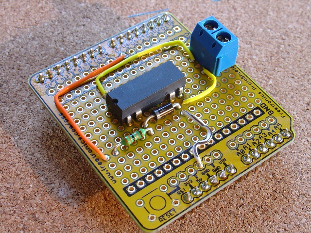
Adruino Garage Door Control (the soldered version) (Click photos for full size images)


For the No Soldering version the top board is this and the Garage Door manual push button is connected to terminal for 1st relay COM1 and NO1 terminals, the 2nd and 3rd terminals from the end of the board. (see photo at the top of this page)
Here is the No Soldering Required parts list of what you need for the NO Soldering version. For the Soldering required parts list see below.
Note: Code revised 21st March 2013 to make pulse reliable. See How to write Timings and Delays in Arduino for the details.
Install the Arduino IDE from http://arduino.cc/en/Guide/HomePage
Open a new File and copy this code to the IDE window, plug in the Arduino Uno via the usb cable and program it. Then un-plug the USB cable.
Set the switches on the Bluetooth board. Set the 3V/5V switch to 5V and set the To Board/To FT232 switch to the To Board position.
Plug the three boards together Arduino, Bluetooth, Relay board. Make sure the pins all line up correctly.
Run wires from the COM1 and NC1 terminals to either side of the Garage Door push button.
Plug the USB wall charger into the Arduino board via the USB cable, so that it will power all three boards.
Download the pfodApp to your Android mobile.
Pair your mobile with the Bluetooth shield and setup a pfod connection called GarageDoor, as described here.
Start pfodApp and click the Open/Close button to open and close the Garage Door.
Finished.
This project demonstrates how simple it is to control your Arduino device from your Andriod mobile by adding a bluetooth module and a small amount of code to make your Arduino device a pfodDevice. In this case the Arduino pulses a relay which is in parallel with the garage door manual push button to open and close it.
pfodDevice's are controlled by a pfodApp. Imagine HTML re-designed for micros with short simple messages each less than 255 bytes to describe the pages. The pfodApp is the micro-browser and the pfodDevice is the micro-server. When the pfodApp running on your Andriod mobile connects, via bluetooth, to your Arduino, the pfodApp sends the request {.} which asks for the pfodDevice's main menu. The pfodDevice return a short messsage (max 255 bytes) which the pfodApp renders to give the user choices that control the pfodDevice. When your user selects a button or menu item, the pfodApp sends the associated command back to your Arduino to execute that function. Commands are typically a single character enclosed by { }. Your Arduino code extracts the command character from this message, using the simple parser below, and executes the associated function.
That's all there is to it. No Android programming is required and the only additional programming you need in your Arduino is the small command parser. All the text and prompts displayed on the Android mobile are completely controlled by the code in the Arduino. The same Andriod pfodApp can control any Arduino or other micro-controller which has been coded as a pfodDevice. If you want to test out how the pfod micro-pages will look on pfodApp, then set up a bluetooth serial connection to your pc as described here and type the micro-pages into the terminal window and see how pfodApp displays them. This also lets you see what messages the pfodApp will return for various user inputs.
As well as navigation buttons and multiple levels of menus, which the parser below handles, the pfod Specification also supports user input such as numbers, text and multi and single selection lists. A slightly larger parser is required to parse user input, see Remote Controlled LCD Display.
The pfod Specification has been designed to keep the micro-controller code (the Arduino code) simple. The micro-controller does not and should not remember the user's navigation history, the Android pfodApp does all that. The micro-controller should simply execute the function associated with the command it is sent and return a result message (often just {} ). See the pfod Specification for all the details and examples.
This example project shows you how to add the simple command parser and the bluetooth module to your Arduino. It also shows you how to build a complete remote garage door opener.
The Adruino Uno pulses a reed relay which is connected across the contacts of the garage door manual push button. When commanded the Arduino code actives the relay for 0.75sec to simulate a manual press of the button to open or close the garage door.
This is the function the user wants to control via their Android mobile. Your other Arduino projects will provide different functions. All you need to do is assign a command to each function and then when the pfodApp requests your main menu, send back a message that will display a helpful prompt to the user and a description of each function available. The user never sees the actual command you have assigned. They choose based on the text descriptions associated with each command.
In this example project the Arduino only provides one function so the options presented to the user are very limited, just one button Open/Close.
Here is what you need for this project:- pfodApp V1.2 from Android Market
Basic electronic tools – soldering iron, solder, long nose pliers, side cutters and a multi-meter (see http://www.ladyada.net/learn/arduino/ ) I also add a flux pen and solder wick
Parts for the remote garage door opener – Ardunio Uno or similar and the Arduino IDE, USB cable, a 9V supply, a bluetooth shield, a shield prototype board and connecting pins and headers, a diode, 33ohm resistor, a 5V reed relay (normally open) and insulated hookup wire.
Here is list of the parts I used and where I purchased them. For the no soldering require use this parts list

(Click
image to open full size image)
In order to communicate with the pfodApp on your Android mobile, the Arduino needs to be coded as a pfodDevice. The pfod Specification details what functionality must be supported in order to be a pfodDevice. As you would expect the requirements for the pfodDevice are minimal
The pfodDevice is required to:-
1. Respond to all
messages, even unrecognised ones, with a reply message. This reply
message can be the Empty message, {}
2. Respond to the
GetMainMenu request, {.} , with a main menu or navigation
input of top level functionality or, less commonly, with one of other
messages:- SingleSelectionList, MultiSelectionList, UpdateMenu
StreamingRawData, StringInput, NumericInput or the Empty message
{}
3. Ignore messages whose length exceeds 255 bytes, including
the start and end { } bytes.
4. If the connection is
half-duplex then the messages from the pfodApp to the pfodDevice take
precedence over, and can interrupt, streaming raw data coming from
the pfodDevice.
For the garage door we will use the command o to pulse the relay. That is when the pfodApp sends {o}, the Arduino code will call the routine that pulses the relay for 0.75sec. The pfodDevice also need to respond to the GetMainMenu request {.} so we need to provide a routine that returns the main menu when the . command byte is parsed.
So the parser needs to parse commands like, { one_byte }. While the pfod Specification supports sending user input such as text and number to the pfodDevice, in many cases the pfodDevice only needs to respond to simple commands of the form { cmd }, where the cmd specifies which function the user wants executed. Commands can be more than one byte long but using just a..z A..Z 0..9 gives 62 unique commands which is more than enough for most devices so this parser shown below will handle the majority of cases. For a complete pfod message parser see Remote Controlled LCD Display.
The cmd parser code for Arduino is:
void parserSetup() {
  parserByteCounter = 0;
  cmdByte = 0; // not started yet
  parserState = pfodWaitingForStart;
  // switch to pfodInMsg when see {
}

//-------------------------------------
//PROCESS_RECEIVED_CHAR
// { char }
// save first char after {
// store in cmdByte
//
// before {  parserState == pfodWaitingForStart
// when { seen parserState == pfodInMsg
// after { first char ( != } ) is stored in cmdByte
// cmdByte returned when terminating } seen but
// not if no } seen for 254 bytes after starting { then
// ignore msg and start looking for { again
//
//-------------------------------------
// return 0 if no cmd found yet
// else return cmd when see }
// or ignore if >254 bytes after {
//
// in is byte read from Serial port
byte parse(byte in) {
  parserByteCounter++;
  if (parserState == pfodWaitingForStart) {
    if (in == pfodStartMsg) { // found {
       parserSetup(); // clean out last cmd
       parserState = pfodInMsg;
    } // else ignore this char as waiting for start {
    // always reset counter if waiting for {
    parserByteCounter = 1;
    return 0;
  }

  // else have seen {
  if ((parserByteCounter == pfodMaxMsgLen) &&
        (in != pfodEndMsg)) {
    // ignore this msg and reset
    // should not happen as pfodApp should limit
    // msgs sent to pfodDevice to <=255 bytes
    parserSetup();
    return 0;
  }

  // else is this the end of the msg
  if (in == pfodEndMsg) {
    byte pfodMsgCmd = cmdByte;
    // this will return 0 when parsing {} msg
    // set up to wait for next {
    parserSetup();
    // return command byte found
    return pfodMsgCmd;
  // else normal byte
  } else if (cmdByte == 0) {
    // save first cmd byte (only the first)
    cmdByte = in;
  }
  return 0;
 }
You can download the complete command parser test sketch from here (pfodDeviceCmdParserTest.zip) or view the sketch as text here. Assuming you have installed the Arduino coding software (see http://arduino.cc/en/Guide/HomePage ) and have successfully run one of the example sketches, copy this code into a new Arduino coding window and load it to your Arduino hardware.
The open the Tools → Serial Monitor and after a few seconds you should see the setup prompt printed on you screen. You can now try typing in some pfod messages and see that they are successfully parsed. Note this parser only records the first byte seen after the starting { and ignores all others up to the closing }. Also as per the pfod Specification if the message exceeds 254 bytes the parser ignores the whole message and waits for the next one.

(click
image for full size image)
When you send {.} the pfodDevice parser responds with Cmd:. Sending {o} the response is Cmd:o Unfortunately the Serial Monitor does not display what you send.
So close the Serial Monitor and open a serial terminal session (e.g. TeraTerm or similar) and connect to the COM port used by the Arduino IDE, in my case COM10 (Look at Tools → Serial Port in the Arduino IDE for your COM port). Set the serial baud rate for the terminal session to 9600, 8bit, no parity, 1 stop bits. Now you can view both what you send and what the response is. If the Arduino board does not respond try pressing the reset button on the board. NOTE: you will need to exit the terminal session before you can reprogram the board again.

The Arduino pfodParseLibraries have a version of this test parser that used the library as an example pfodParser.
Now that we have the parser running all that is left to do is code the routines that will execute the commands sent to by the pfodApp to this pfodDevice. Only two messages need to be handled:- The request for the main menu, {.} (all pfodDevices must handle this) and the request to Open/Close the door, {o}.
The parser will return the characters . and o when it parses these two messages, so lets add two routines to handle these. If the parser returns any other character that our pfodDevice does not support we will just return {}. Although we don't expect to get any types of messages, pfodDevices must respond to all messages received so we will just return an empty message as a response as per the pfod Specification
When our pfodDevice gets the
request for the main menu, it will respond with a Navigation menu
which only has a Home button
{^Press
to open or close|||||o~Open/Close}
the
left, right, up, down buttons are missing. Again see the pfod
Specification for all the details of this and the other possible
messages. The Home button will show the text “Open/Close”
and has the command o
associated with the button.
When the user presses that button the pfodApp will send {o} to the pfodDevice. So we need to add code for to produce the 0.75sec pulse on one of the output pins to turn the relay on short out the contacts on the Garage Door's manual push button to open or close the garage door.
There is the final sketch. When you load and run this sketch, put a volt meter between Digital I/O pin 7 and GND. Then when you send {o} via the Serial Monitor you will see the volt meter show +5V for a short time. If your digital volt meter is a bit slow to respond you can temporally increase the pulse length to 2 secs. to make it easier to see. Here is the Serial Monitor output for the two commands {.} and {o} and below that the terminal session showing the input as well as the response.


That's it coding finished. Now all you need to do is wire up the shield board, test the relay is switching and then that you can connect from your Android phone.
If you are making the No Soldering Required version then just skip this step and plug in the 4 relay shield from SeeedStudio. NOTE: Place 2 layers of electrical tape on the top of the Arduino's usb connector. This will prevent the relay shield from making contact. Now when you power up your board with the shield attached, but no bluetooth module yet, and send the {o} cmd, then a resistance (ohm) meter across the screw terminals COM1 and NO1 should register zero ohms as the relay pulses.
If you are making the soldering required version continue here.
Here is the circuit and layout of the relay shield that will open the garage door remotely using the sketch described above.

 (Click images to open full size pdfs)
Wire up the prototype board as shown in these pdfs. Double check the direction of the diode. The bar end of the diode should connect to the 33Ohm resistor.
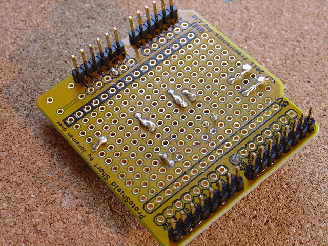 (Click images to open full sized image)
Now when you power up your board with the shield attached, but no bluetooth module yet, and send the {o} cmd, then a resistance (ohm) meter across the screw terminal should register zero ohms as the relay pulses.
The bluetooth module I used was the iteadstudio.com Stackable Bluetooth Shield : BT Shield v2.1 (Slave) Set the 3V/5V switch to 5V and set the To Board/To FT232 switch to the To Board position. Check you have set the module for 5V or you will damage it.
The bluetooth module needs to be configured to run at 9600baud, fortunately the iteadstudio slave bluetooth module is already configured to 9600 baud so there is nothing to do here. (If you do need to configure the iteadstudio switch the To Board/To FT232 switch to “To FT232”. You can now use the terminal program to configure the bluetooth module.)
Un-plug the USB cable and plug the bluetooth sheild into you Arduino and then plug your relay shield on top of the bluetooth shield. Connect a power supply 7V to 9V see http://www.ladyada.net/learn/arduino/starterpack.html for how to connect this.
Load pfodApp onto your Android mobile and pair with this bluetooth module. Then set up a pfodApp connection for “Garage Door” as described in the pfodAppForAndroidGettingStarted.pdf guide.
That's it. Finished. Now when you open the pfodApp on your mobile and connect to the “Garage Door”, the pfodApp should come up with the Open/Close button for you to control the garage door.
But
wait! What about those debugging print statements in the code?
Because they are outside the message start and end, { }, characters, they are ignored by the pfodApp. However the pfodApp still captures them in the pfodApp's Debug screen, accessed from the mobile's menu button. You can comment them out in the code when you are satisfied every thing is working.
The basic controller described above just provides an open/close function. As an extension you could also add limit switches to detect when the door was fully open or fully closed and feed that information back to the pfodApp. When you send the mainMenu response from the pfodDevice, you can also include a re-request time. Then the pfodApp will re-request that page at that time interval. This lets the pfodDevice update the page with the doors position each time it is re-requested. See the pfod Specification for more details.
AndroidTM is a trademark of Google Inc. For use of the Arduino name see http://arduino.cc/en/Main/FAQ
The General Purpose Android/Arduino Control App.
pfodDevice™ and pfodApp™ are trade marks of Forward Computing and Control Pty. Ltd.

Contact Forward Computing and Control by
©Copyright 1996-2024 Forward Computing and Control Pty. Ltd.
ACN 003 669 994