
|
Home
| pfodApps/pfodDevices
| WebStringTemplates
| Java/J2EE
| Unix
| Torches
| Superannuation
|
| About
Us
|
|
|
Android controlled Lights and Power
|
by Matthew Ford 2nd February 2015
(original 1st November 2012)
© Forward Computing
and Control Pty. Ltd. NSW Australia
All rights reserved.
Note: Check out pfodDesigner for a quick way to create custom Android menus to switch stuff on and off.
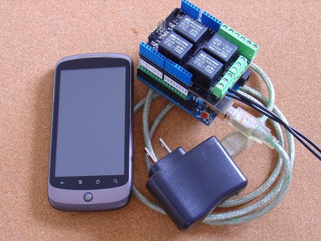
Android remote control screen
(customized to control the garaged door and lights) – the
pfodApp
available from the Android
Market
and Adruino Power Relays.
This page has been updated to replace the discontinued relay shield with the Seeed Studio Relay shield V2 .
You can give each relay your own personal name by editing the Arduino code as shown below. No Android programming is required. An electrician should mount the project in a suitable insulated box and wire the four relays across the switches of the lights and/or power points you want to control. This project is in three parts.
The basic control of 4 switches, called switch 1, switch 2, switch 3 and switch 4. This is what you get from the Quick Start below.
Customizing the names of your switches to give them meaningful names.
Making one of the switches a Garage Door opener and the other three the Outside Light, Garage Light and Hall Light (shown above) or what ever name your want.
No Android programming is required to make and any of these three versions. Simple changes to the Arduino code completely controls what options are presented on the user's mobile.
By adding a bluetooth module and a small amount of code to make your Arduino device a pfodDevice, you can control your Arduino project from your Android mobile, in this case the Arduino turns relays on or off and pulses a relay which is in parallel with the garage door manual push button to open and close it.
pfodDevice's are controlled by a pfodApp. Imagine HTML re-designed for micros with short simple messages each less than 255 bytes to describe the pages. The pfodApp is the micro-browser and the pfodDevice is the micro-server. When the pfodApp running on your Andriod mobile connects, via bluetooth, to your Arduino, the pfodApp sends the request {.} which asks for the pfodDevice's main menu. The pfodDevice return a short messsage (max 255 bytes) which the pfodApp renders to give the user choices that control the pfodDevice. When your user selects a button or menu item, the pfodApp sends the associated command back to your Arduino to execute that function. Commands are typically a single character enclosed by { }. Your Arduino code extracts the command character from this message, using the simple parser below, and executes the associated function.
That's all there is to it. No Android programming is required and the only additional programming you need in your Arduino is the small command parser. All the text and prompts displayed on the Android mobile are completely controlled by the code in the Arduino. The same Andriod pfodApp can control any Arduino or other micro-controller which has been coded as a pfodDevice. If you want to test out how the pfod micro-pages will look on pfodApp, then set up a bluetooth serial connection to your pc as described here and type the micro-pages into the terminal window and see how pfodApp displays them. This also lets you see what messages the pfodApp will return for various user inputs.
As well as navigation buttons and multiple levels of menus, which the parser below handles, the pfod Specification also supports user input such as numbers, text and multi and single selection lists. A slightly larger parser is required to parse user input, see Remote Controlled LCD Display.
The pfod Specification has been designed to keep the micro-controller code (the Arduino code) simple. The micro-controller does not and should not remember the user's navigation history, the Android pfodApp does all that. The micro-controller should simply execute the function associated with the command it is sent and return a result message (often just {} ). See the pfod Specification for all the details and examples.
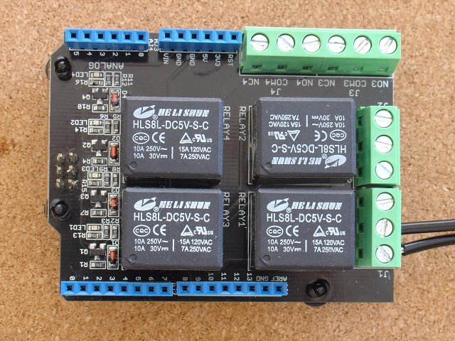
The Relay Shield V2 is provided with 4 relays rated at 10A, 240 AC and so are suitable for switching 240V devices. My Relay Shield was delivered with headers soldered in place and with clear insulation on the bottom of the board.
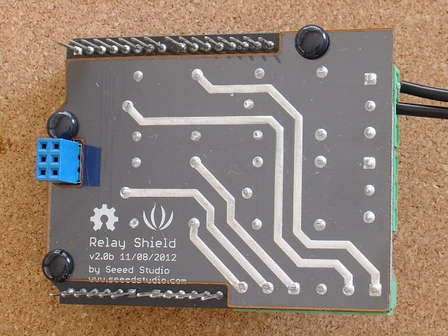
A
printed circuit board (PCB) designed for mains voltage would normally
have optically isolated control inputs to help protect the computer
from mains surges and lighting strikes and the PCB would be laid out
to maximize the distance between the high voltage lines and the low
voltage control lines. The Relay Shield PCB board has been designed
for small size rather than for maximum electrical isolation and does
not use optically isolation between the inputs and the relays. What
this means is that while the relay shield can switch 10A, 110/120V AC
it is more susceptible to damage from power surges and lightning
strikes. The point to realize is that even an optically isolated well
spaced out relay board can be destroyed by a power surge / lightning
strike.
I have personal experience of a lighting strike on the power line just outside the house which destroyed the stove, tv, computer and printer, everything that was turned on. All of which were designed for 240V operation with the recommend clearances. In the case of the stove, the lightning melted a hole the size of my fist in the back panel.
So in summary you can use this relay board for switching 10A 240V AC but make sure it is mounted in a mains rated insulated box and don't leave is connected to your PC. Since this project uses bluetooth to control the relays from your Android mobile, it is designed to be isolated from other electronic equipment.
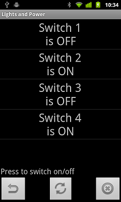
This quick start will give you control of 4 switches from your Android mobile. The switches are named Switch 1, Switch 2, Switch 3 and Switch 4 and correspond to the Relay board terminal blocks 1,2,3 and 4. The Android pfodApp shows the current state of each switch, ON or OFF. The next step in this tutorial shows you how to set your own names for the switches.
Here is the parts list of what you need.
Install the Arduino IDE from http://arduino.cc/en/Guide/HomePage
Open a new File and copy this code to the IDE window, plug in the Arduino Uno via the usb cable and program it. Then un-plug the USB cable.
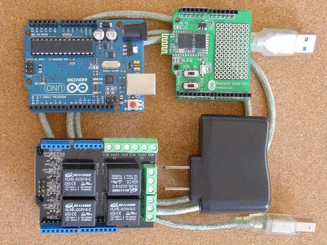
Set the switches on the Bluetooth board. Set the 3V/5V switch to 5V and set the To Board/To FT232 switch to the To Board position.
Plug the three boards together Arduino, Bluetooth, Relay board. Make sure the pins all line up correctly..
Plug the USB Wall Charger into the Arduino board via the USB cable, so that it will power all three boards.
Download the pfodApp to your Android mobile.
Pair your mobile with the Bluetooth shield and setup a pfod connection called Lights and Power, as described here.
Start pfodApp and click the Switch 1 to 4 buttons to turn the relays on and off. Check between COM and NC terminals for terminals 1 to 4 with a multi-meter on Ohms.
Have an electrician install in a mains rated box and wire the relays to the lights/power points you want to control. If you want to customize the names of the switches proceed to the next step before installing.
Finished.
The quick start build just used generic names of Switch 1 to Switch 4. However it is easy to give the switches your own unique names.
Open the code in the Arduino IDE
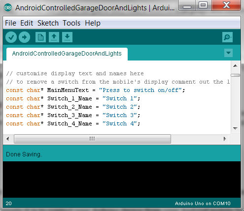
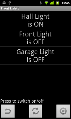
and edit the Switch Name text to whatever you want. For example here I have named Switch 2,3 and 4 as “Front Light”, “Garage Light” and “Hall Light” and saved the file as FrontLights.

Switch 1 is not used in this example so to prevent it from being displayed by the Android mobile pfodApp, I commented out the code that adds that menu item to the message sent to the mobile.

The completed FrontLights code is here. Then when you connect your Android mobile pfodApp, it displays
Finally here is the code that combines a garage door opener with the control of the front lights. It combines the Android controlled Garage Door opener, which uses relay 1, with the Front Lights code from part 2). (Note: the code was broken between 5th January 2015 and 2nd February 2015, fixed now.)
That is the final example code.
Next I will discuss how the Android pfodApp displays the relay states and controls the relays. All the code examples above are complete in themselves, no libraries are needed. However there are libraries available for the pfodDevice command parser if you want to use them. Examples of using these libraries are given in Garage Door Remote and in Remote Controlled LCD/LED Display. The Arduino pfod libraries are available here.
In order to communicate with the pfodApp on your Android mobile, the Arduino needs to be coded as a pfodDevice. The pfod Specification details what functionality must be supported in order to be a pfodDevice. As you would expect the requirements for the pfodDevice are minimal
The pfodDevice is required to:-
1. Respond to all
messages, even unrecognised ones, with a reply message. This reply
message can be the Empty message, {}
2. Respond to the
GetMainMenu request, {.} , with a main menu or navigation
input of top level functionality or, less commonly, with one of other
messages:- SingleSelectionList, MultiSelectionList, UpdateMenu
StreamingRawData, StringInput, NumericInput or the Empty message
{}
3. Ignore messages whose length exceeds 255 bytes, including
the start and end { } bytes.
4. If the connection is
half-duplex then the messages from the pfodApp to the pfodDevice take
precedence over, and can interrupt, streaming raw data coming from
the pfodDevice.
As an example we will look at the pfodDevice code for the combined garage door opener and lights control.
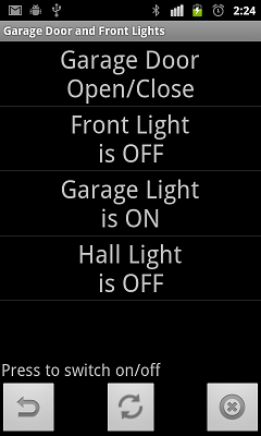
First the pfodDevice needs to respond to the {.} message that the pfodApp on your Andriod mobile sends when it connects. This requests the pfodDevice's main menu. In this case we want to display 4 buttons (menu items), with the names of the switches and their current state, On or Off.
Each of these buttons has a unique command associated with it which is not displayed to the user. When the user selectes that menu item, the associated command is send back to the pfodDevice (Arduino Uno) to be executed. In this case the commands '1', '2', '3' and '4' are used for the each of the 4 relay. So a typical main menu message would look like
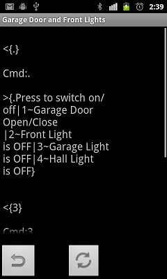
This is a screen shot from the
debug screen of the pfodApp. The pfodApp debug screen is accessed
from the mobiles menu button. When the pfodApp connected to the
Arduino pfodDevice, the pfodApp send the {.}
message to request the pfodDevice's main menu. The pfodDevice parser
parses the Cmd: . and the Adruino code prints out the result. The
pfodApp on the Android mobile ignores this text since it is not
contained within pfod message start and end chars, {
} . The pfodDevice then returnes its
main menu
{.Press to switch
on/off|1~GarageDoor\nOpen/Close|2~Front Light\nis OFF|3~Garage
Light\nis OFF|4~Hall Light\nisOff}
where
\n starts a new line. The {. indicates that this message should be
displayed as a list of menu items, buttons. The next 4 sections
between | | define each menu item. Each menu item is made up of the
command
~ display
text.
See the pfodSpecification
for a detailed description of this menu message. First part is the
command to be sent back when this menu item is selected and then the
text to display. So for example 2~Front
Light\nis OFF sets
2
as the
command for this menu button and set the text as
Front
Light
is Off
When the user selects this menu item, the pfodApp send the associated command 2, in the message {2}, to the pfodDevice. The pfodDevice command parser parsers the command and activates the relay and sends back an updated menu to display to the user, showing that the Front Light is now ON.
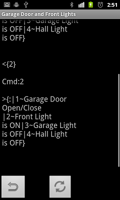
When the Garage Door Open/Close button is pressed the pfodApp sends the msg {1} to the pfodDevice, which parse the message and pulses the relay connected to the garage door push button to open/close the door.

Notice in this case the Arduino code prints when it starts and ends the pulsing of the relay. Again the pfodApp ignores this extra text as it is not contained within the pfod message start and end characters { } . See Android controlled Garage Door opener for a more details on the Garage Door pulse code.
AndroidTM is a trademark of Google Inc. For use of the Arduino name see http://arduino.cc/en/Main/FAQ
The General Purpose Android/Arduino Control App.
pfodDevice™ and pfodApp™ are trade marks of Forward Computing and Control Pty. Ltd.

Contact Forward Computing and Control by
©Copyright 1996-2020 Forward Computing and Control Pty. Ltd.
ACN 003 669 994