
|
Home
| pfodApps/pfodDevices
| WebStringTemplates
| Java/J2EE
| Unix
| Torches
| Superannuation
|
| About
Us
|
|
|
Arduino for Beginners, controlled by Android
|
by Matthew Ford 12th October 2013
(original1st September 2013)
© Forward Computing and Control
Pty. Ltd. NSW Australia
All rights reserved.
This page follows on from Arduino for Beginners, controlled by Android, and explains a simple Arduino sketch that lets you switch a digital output on and off from your Android mobile phone. This page also covers debugging your sketch while connected to your mobile.
Once you understand this basic sketch you can use it a basis for your own projects. No Android programming is required, but using pfodApp you can easily customize the mobiile's display by changing text strings in your Arduino sketch.
This project uses the same parts as Arduino for Beginners, controlled by Android and assumes you have already built that project


Here is modified version of the
standard BLINK example. This version lets you turn the Led on and off
from your mobile.
The sketch
source is here, copy and paste it into the IDE and load it on to
you Uno board.
You
also need to download the pfodParser
library zip file and install it following the instructions on
that page.
NOTE:
remove the bluetooth shield before uploading the sketch because the
bluetooth shield uses the same pins the USB connection does and the
programming get confused.
#include <EEPROM.h> // include the EEPROM library
#include <pfodParser.h> // include the library
pfodParser parser;  // create the cmd parser

// Pin 13 has an LED connected on most Arduino boards.
// give it a name:
int led = 13;

// the setup routine runs once when you press reset:
void setup() {
  Serial.begin(9600);
  for (int i=3; i>0; i--) {
    // wait a few secs to see if we are being programmed
    delay(1000);
  }
  // initialize the digital pin as an output.
  pinMode(led, OUTPUT);
}

// the loop routine runs over and over again forever:
void loop() {
  byte in = 0;
  byte cmd = 0;
  if (Serial.available()) {
    in = Serial.read(); // read the next char
    cmd = parser.parse(in); // pass it to the parser returns non-zero when a command is fully parsed
    if (cmd != 0) { // have parsed a complete msg { to }
      if ('.' == cmd) {
        // pfodApp sent {.} it is asking for the main menu
       // the complete messages is  {.Turn Led On or Off||o~Toggle Led}
        Serial.print(F("{."  // {. msg tells pfodApp to display a menu screen
       "Turn Led On or Off"  // this is the title of the screen
       "|o~Toggle Led"       // this is the menu, cmd is o text is Toggle Led
                             // you can add more menu items here
       "}"));               // this finishes the msg
      } else if ('o' == cmd) {
        // pfodApp sent {o} i.e. user clicked on On/Off menu item
        // note o was the cmd associated with the Toggle Led menu item above
        boolean ledState = digitalRead(led);
        if (ledState == LOW) {
          digitalWrite(led,HIGH); // was off turn on
        } else {
          digitalWrite(led,LOW); // was on turn off
        }
        Serial.print(F("{}")); // always return a response otherwise pfodApp times out and disconnects

       // you can add more command handlers here match the cmd to the menu cmd above
      } else {
        // don't recongnize this command just ignore and return empty response;
        Serial.print(F("{}")); // otherwise pfodApp times out and disconnects
      }
    }
    cmd = 0; // have processed this cmd now
    // so clear it and wait for next one
  } // else no serial chars just loop
}
Note: in the code above all the strings are enclosed with F(“ “) This macro makes sure the strings are placed in the program FLASH where you have much more room. (See What fails when you add lots of Strings to your Arduino program.)
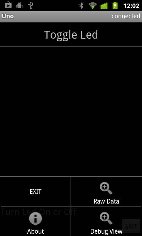
Install pfodApp on your mobile and set up a connection to your bluetooth shield as described in the pfodAppForAndroidGettingStarted.pdf. I called my connection Uno. Click on the connection to connect and the sketch above will return the menu below.

Clicking the “Toggle Led” menu turns the Uno led on and off. (The led is near the USB connection and partially hidden by the bluetooth shield.)
Lets have a look at the messages being sent to and from the pfodApp on your mobile. Open the Debug View from your mobile's menu button.
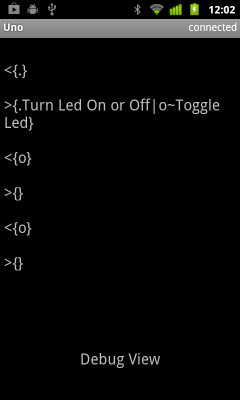
The Debug View shows all the messages to and from the pfodApp. The < indicates messages from the pfodApp on your mobile to the pfodDevice, the Uno. The > indicates messages from your Uno sketch to the pfodApp on your mobile.
As you can see from the screen shot above. The first
message the pfodApp sends, once it connects, is {.} This is
the request for the pfodDevices main menu. In the sketch the parser
parses this message and once the closing } is seen the parser returns
the command, . (dot). The sketch then returns its main menu
{.Turn
Led On or Off||o~Toggle Led}
This tells the pfodApp to display a menu screen with the menu item “Toggle Led” The command associated with this menu item is 'o'. See the pfod Specification for the details and examples of all the pfod messages and their formats.
When you click on that menu item, the pfodApp sends the associated command to the pfodDevice, {o} The parser parses it and sets the cmd byte to 'o' once the closing } is received. The sketch then toggles the led on or off and, most importantly, returns an empty message, {}
Every message from the pfodApp to the pfodDevice must be responded to, otherwise the pfodApp will timeout waiting for a response and think the connection is broken. If there is nothing else to return the just return an empty message, {}
A limitation of the first sketch
is that unless you are looking at the Uno board, you cannot tell if
the led is on or off. We will fix that with this second sketch.
Open
the SecondDigitalOutputSketch.ino
and copy and paste it into the IDE and load it on to you Uno board.
(Remember to remove the Bluetooth Shield when re-programming the Uno)
Here are the changes:-
      if ('.' == cmd) {
        // pfodApp sent {.} it is asking for the main menu
       // the complete messages is  {.Turn Led On or Off||o~Turn Led ... }
        Serial.print(F("{.Turn Led On or Off|o~Turn Led "));
        // here insert the appropiate word ON or OFF
        if (digitalRead(led) == LOW) {
          // next click will turn it on
          Serial.print(F("ON"));
        } else {
          // next click will turn it off
          Serial.print(F("OFF"));
        }
        // finally close the message with }
        Serial.print(F("}"));
      } else if ('o' == cmd) {
        // pfodApp sent {o} i.e. user clicked on On/Off menu item
        // note o was the cmd associated with the Toggle Led menu item above
        if (digitalRead(led) == LOW) {
          digitalWrite(led,HIGH); // was off turn on
          // now update the menu with the menu text
          Serial.print(F("{:|o~Turn Led OFF}"));
        } else {
          digitalWrite(led,LOW); // was on turn off
          // now update the menu with the menu text
          Serial.print(F("{:|o~Turn Led ON}"));
        }

       // you can add more command handlers here match the cmd to the menu cmd above
      } else {
        // don't recongnize this command just ignore and return empty response;
        Serial.print(F("{}")); // otherwise pfodApp times out and disconnects
      }
When the pfodApp asks for the main menu, the sketch now checks to see if the Led is on or off. If it is off (digital output LOW) the menu item says “Turn Led ON” otherwise the menu items says “Turn Led OFF”. So when you connect your mobile, the menu will tell you if the led is on or off.
The second change to the sketch is what is returned to the pfodApp after you click the menu item and send the{o} message to the pfodDevice (Uno). In the first sketch we just returned an empty messsage, {}. However if we continue to do that the menu item will not reflect the new state of the Led. So this time the sketch returns an UpdateMenu message, {: These messages do not display a new menu, they just update an existing menu.
You can update any part of the existing menu screen,
the title, the individual menu item texts, etc. You cannot add new
menu items but you can hide and reveal menu times by updating their
text to blank to hide them and non-blank to reveal them. In this case
we just want to update the text of the one existing menu item.
If
we just turned the led on then we update the text to “Turn Led
OFF” using the message {:|o~Turn Led OFF}
If we just
turned the led off then we update the text to “Turn Led ON”
using the message {:|o~Turn Led ON}
Here is what the menu and debug view looks like:-


There are lots of other screens you can specify in your sketch, like slider menu items, multi-selection lists etc, but many projects just need a few buttons to control them and this sketch will serve as a good starting point.
One last point to cover is debugging. Arduino uses the traditional method of debugging. That is adding print statements in the code to display what it is doing. When you are connected to your Uno board via the bluetooth shield all the print statements are sent to the bluetooth connection.
This is just fine because they will turn up on your mobile's Debug View in pfodApp. If you avoid the { character in your debug statements, they won't be confused for pfod messages and the pfodApp will just ignore them.
The sketch DebugDigitalOutputSketch.ino contains some extra debugging print statements. Copy and paste it into the IDE and load it on to you Uno board. (Remember to remove the Bluetooth Shield when re-programming the Uno) When you connect again the menu looks the same but if you open the DebugView you will see the extra debug statements together with the pfod messages.

There
is also another screen accessible from your mobile's menu and that is
the Raw Data view. This view shows just the text that was NOT part of
a pfod message.

In
this case just the debugging printout. When you open this screen it
starts saving the Raw Data to a file on your mobile for latter
downloading to your computer (see pfodAppForAndroidGettingStarted.pdf
for details on how to download it). Once you have finished debugging,
this raw data screen is also useful for logging measurements your
Arduino is making. See Mobile
Data Logging using pfodApp, Android and Arduino for an example.
One final note. A common error when using pfod messages is to forget to send the closing }. In these cases the pfodApp will timeout and close the connection, however you can still acces the Debug View after the connection times out to see just what was sent and not sent.
To learn more about coding Arduino
see http://arduino.cc/en/Tutorial/HomePage
To learn more about pfod check out the pfod
Specification and the projects on www.pfod.com.au
AndroidTM is a trademark of Google Inc. For use of the Arduino name see http://arduino.cc/en/Main/FAQ
The General Purpose Android/Arduino Control App.
pfodDevice™ and pfodApp™ are trade marks of Forward Computing and Control Pty. Ltd.

Contact Forward Computing and Control by
©Copyright 1996-2020 Forward Computing and Control Pty. Ltd.
ACN 003 669 994