
|
Home
| pfodApps/pfodDevices
| WebStringTemplates
| Java/J2EE
| Unix
| Torches
| Superannuation
| CRPS Treatment
|
| About
Us
|
|
|
How to debug Pi Pico with Arduino
|
by Matthew Ford 14th Sept 2025 (14th
Sept 2025)
© Forward Computing and Control Pty. Ltd. NSW
Australia
All rights reserved.
The tutorial covers, step by step, setting up Arduino on Windows 10 to program and debug Raspberry Pi Pico, Pi Pico W and P Pico 2 W boards. It will cover the following topics
Installing the Arduino Board Support for Rasbery Pi Pico
Help My Serial Port is Missing
Building Pi PicoProbe (CMSIS-DAP)
Debugging Blink with Arduino V2 – Breakpoints
Debugging ASCIITable – Serial Output
Target Board – Pi Pico or Pi Pico W (used in this tutorial) or Pi Pico 2 W
Debug Probe – Pi Pico 2020 ~US$4 (used in this tutorial) or Pi Pico 2 ~US$5 or Raspberry Pi Debug Probe ~US$12 (Also see the Raspberry Pi Debug Probe product page)
Arduino IDE V1.8.19 – for initial setup
Arduino IDE V2.3.6 – for debugging
Pi Pico Board support V5.1.0
Pi Pico Debug Probe Software V2.2.3
Zadig V2.9 – driver updates for Windows 7 (not needed for Windows 10)
While the debugging will eventually be carried out using Arduino V2 IDE, Earle Pillhover suggests first installing the board support on Arduino IDE V1.8.. to ensure all the drivers are present. The latest Arduino V2 IDE may have fixed this issue but this tutorial carries out the first install and testing on Arduino IDE V1.8.19.
Install Arduino
IDE V1.8.19
Follow Installing
Pi Pico support via Arduino Boards Manager instructions to add
the Pi Pico board support and drivers.
Select your target board from the list of Rasberry PI RP2040 boards. In this case Pi Pico W
Open the File → Examples → Basic → Blink example.
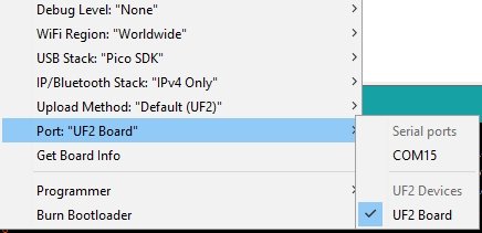
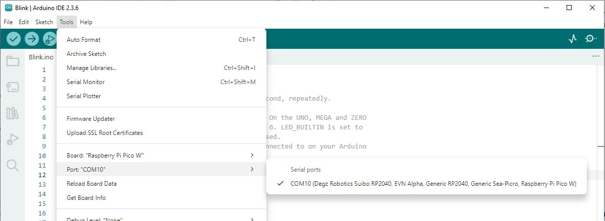
While holding down the Boot push button, plug in your target board. The tools menu should show
Upload the Blink sketch to Pi Pico board. The board led should start blinking.
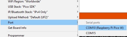
Opening the Port: option again should now show the the COM for the Raspberry Pi board
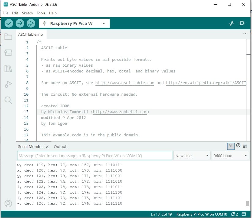
Check the Serial connection by opening the File → Examples →
Communication → ASCIITable example and upload to the Pi Pico
board.
Open the Serial Monitor to see the ASCII table displayed.
You usually do not need to re-connect the board with the Boot button held down (other than the first time) and can now just leave the port selection as COM10 (Raspberry Pi Pico .. ). However if you loose the COM port setting (see below), you can re-connect with the Boot pushbutton held down to force the board back into UF2 Board mode for programming.
Having tested programming your Pi Pico board with Blink and ASCIITable sketches, the most common cause of missing Serial port after programming is that the program has failed to run. Being C++, just because your program compiles does not mean it will actually run. In this case go back to a know valid program, like Blink or ASCIITable and check that works and slowly add the changes from there, OR move on the debugging the program with Arduino IDE V2.
Another thing to check is that the USB cable is OK. Try a different cable and/or a different port.
To debug Pi Pico board with Arduino, you need to install Arduino IDE V2. Here Arduino IDE V2.3.6 was used. Other versions will have their own set of features/bugs.
Follow the Arduino IDE Installation Warning instructions for installing the Arduino IDE V2.
“Please do not use the Windows Store version of the actual Arduino application because it has issues detecting attached Pico boards. Use the “Windows ZIP” or plain “Windows” executable (EXE) download direct from https://arduino.cc. and allow it to install any device drivers it suggests. Otherwise the Pico board may not be detected. “
You do not need to re-install the Pi Pico board support as Arduino IDE V2 uses the same Arduino15 package directory to find installed board packages.
Opening Arduino IDE V2 should show the same COM port for the Pi Pico.
Note: The Tools → Upload Method is Default UF2
This
is the normal method for programming Pi Pico boards directly. It will
change later for uploading / debugging via a Pi PicoProbe.
Check that Blink and ASCIITable sketches still upload and run.
For some reason Arduino IDE V2 can take a few seconds to display
the File menu when you click on File
If
you think you did not click and click a second time it will not open
at all. So just click once deliberately and wait. The other menus
seem to respond normally.
In order to debug Pi Pico boards via Arduino IDE V2, you need a CMSIS-DAP interface board with connects OpenOCD to the SWD interface on the Pi Pico target board. This project, which uploads programs to nRF52832 chips, uses a MuseLab DAPLink (CMSIS-DAP) programmer. That module implements CMSIS-DAP, but an older version (at least the module that was purchased 2022 did) that does not implement command 0x01 and so does not work with the version of OpenOCD supplied with this board support.
There are three inexpensive options for a CMSIS-DAP module to allow you to load and debug programs using the Arduino IDE V2. Modules build on Pi Pico 2020 ~US$4 (used in this tutorial) or Pi Pico 2 ~US$5 or Raspberry Pi Debug Probe ~US$12. These modules are first programmed with the a code package to turn them into CMSIS-DAP programmers/debuggers.
Here a Pi Pico 2020 is used. (See Raspberry Pi Debug Probe product page for details on how connect it up if you are using that one)
The Raspberry DebugProbe release page contains the latest code versions for Pi Pico 2020, Pi Pico 2 and Pi Debug Probe. Here V2.2.3 debugpobe_on_pico.uf2 for the Pi Pico (not Pi Pico 2) was used (local copy here)
To load the uf2 file, hold down the boot push button and connect the USB to the Pi Pico 2020. A drive folder will open
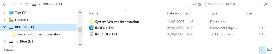
Drag and drop (or copy/paste) the debugpobe_on_pico.uf2 to that folder to upload the debug probe support. The folder will close.
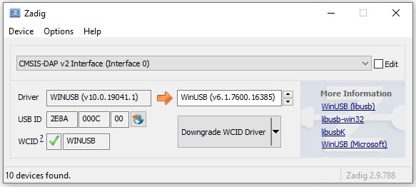
You can check the driver installation by opening Zadig V2.9 and choosing Options → All Devices will show CMSIS-DAP V2 in the drop down list.
For Windows 10 DO NOT Downgrade the driver This is just to check the driver is installed if you have problems getting the upload/debugging running.
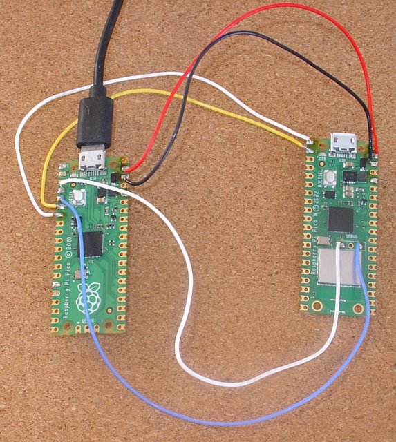
To upload and debug using the Pi Pico DebugProbe, you need to wire up the SWD interface of the target device. This consists of 4 wires, Power and GND and SWDIO and SWCLK.
On the Pi Pico Debug Probe,
GPIO2 is the SWCLK and GPIO3 is the SWDIO. These need to be wired to
the SWCLK and SWDIO pins (solder points) on the target board.
NOTE:
The SWCLK pin on the target board
is indicated with an Arrow (V)
The three SWD pin names are marked on the back of the board. On a Pi Pico and Pico 2 target boards the SWD pins are at the end of the board. On Pi Pico W and 2 W boards, the antenna is at the end of the board and the three SWD pins are in the center of the board. The center pin of the three is the GND pin. That GND pin does not need to be connected as the Power/Gnd connections below supply the GND connection.
For Power / GND wire VSYS and GND on Pi Pico Debug Probe to VSYS and GND on the target board.
|
Pi Pico |
Target Board |
|---|---|
|
GPIO2 |
SWCLK |
|
GPIO3 |
SWDIO |
|
GPIO4 |
TX (GPIO0) |
|
GPIO5 |
RX (GPIO1) |
|
VSYS |
VSYS |
|
GND |
GND |
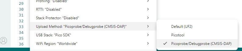
Having wired up the Pi Pico DebugProbe, plug in its USB connection (leave the target's USB un-connected) and in Arduino IDE, and under Tools select Picoprobe/Debugprobe (CMSIS-DAP) for the Upload Method
Also select Sketch → Optimize for Debugging
NOTE: DO NOT Enable Tools → Stack Protections as the sketches will not run with this enabled. See this issue
Click the Upload → button to compile and upload the Blink
sketch.
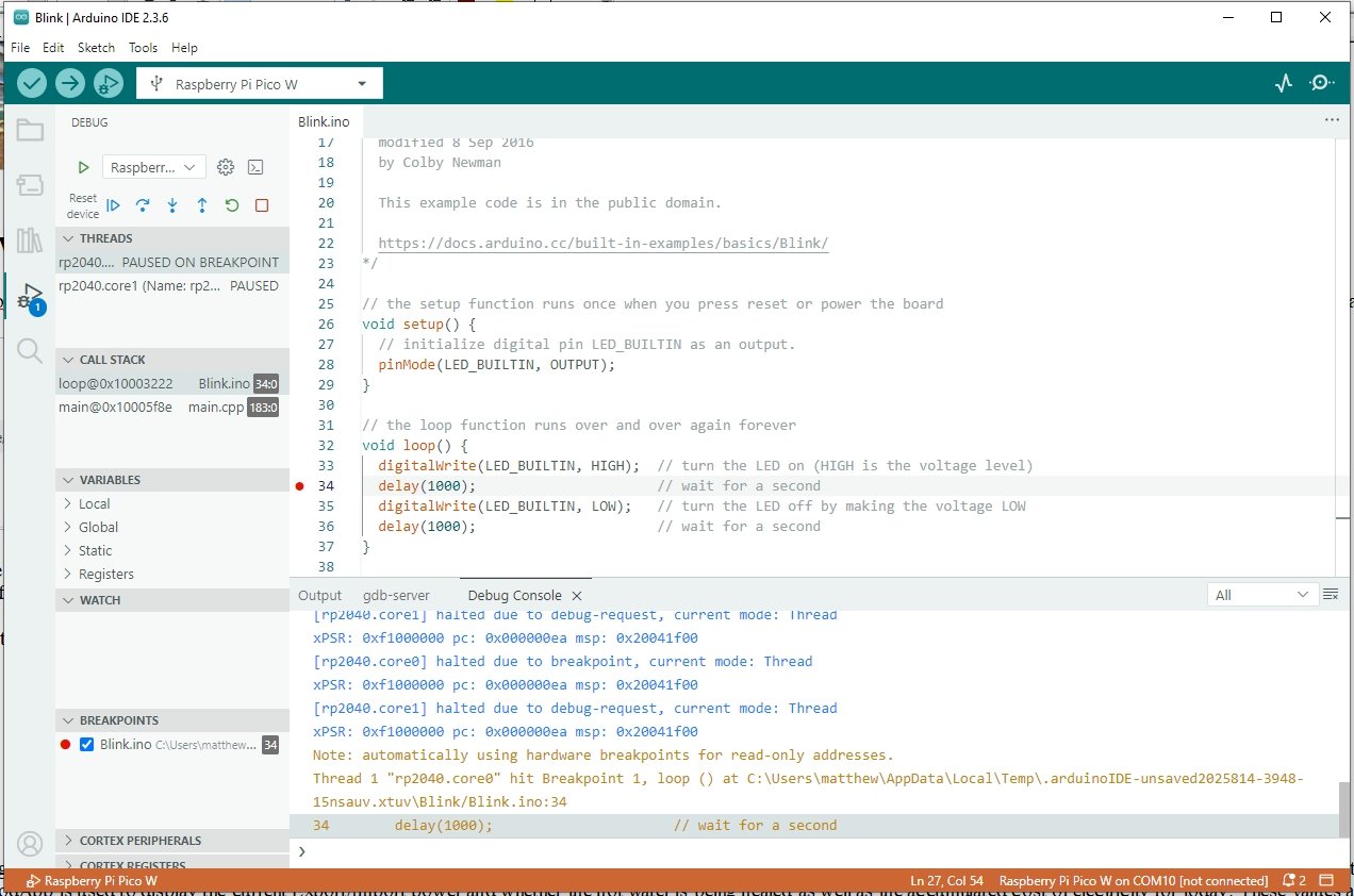
Open the debug tab and click to the left of the line
number 34 to add a breakpoint on delay(1000);
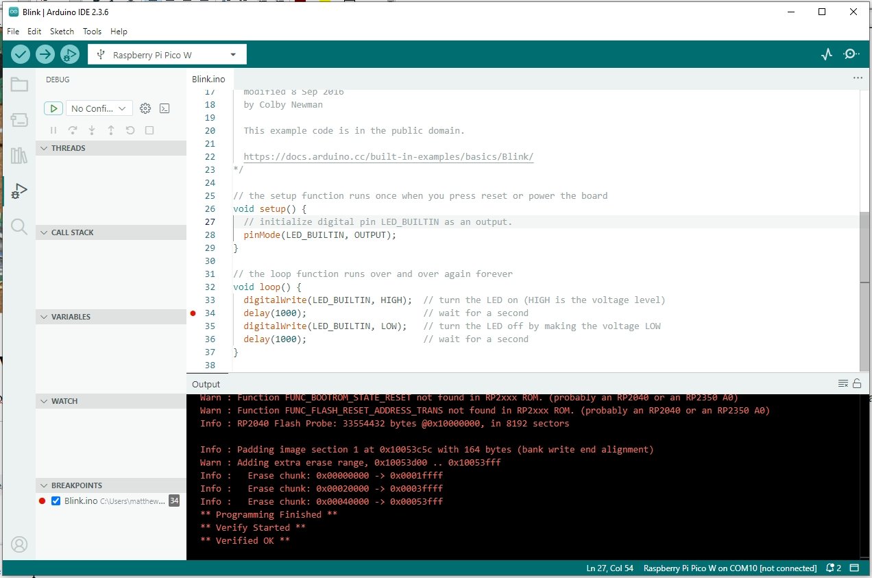
Click the Debug Button (at the top, to the right of the → upload button) to start debugging the program. The program will stop on the breakpoint. The led will be on, not blinking
From there you can continue, step over, step into methods, view variables etc. See Debugging with the Arduino IDE 2 for more details.
The ASCIITable sketch outputs the table to the USB Serial connection. However while you are debugging, just plugging the target's USB into the computer will not give you the Serial output. You need to re-direct the Serial output to Serial1, pins GPIO0 (TX) GPIO1 (RX) and wire those pins on the target to the Pi Pico DebugProbe pins GPIO6 → RX and GPIO7 → TX
Of course you need to now have the serial output that used to go to Serial, be redirected to Serial1
For simple sketches, you can easily do this by redefining Serial to be Serial1. For example in ASCIITable.ino, below all the #includes, if any, add #define Serial Serial1 see ASCIITableSerial1.ino
#define Serial Serial1

void setup() {
 //Initialize serial and wait for port to open:
 Serial.begin(9600);
 while (!Serial) {
  ; // wait for serial port to connect. Needed for native USB port only
 }
. . .
For more complex sketches with multiple files etc, you can add a Stream* debugPtr and assign either &Serial or &Serial1 to it and then use that for all your debug output. See ASIITableDebug.ino
// #define DEBUG if debugging via pico debugprobe, will direct serial to Serial1
#define DEBUG
Stream* debugPtr = NULL; // no debug to start with

void setup() {
 //Initialize Serial1 if debugging, else Serial
#ifdef DEBUG
 Serial1.begin(9600);
 debugPtr = &Serial1;
#else
 Serial.begin(9600);
 debugPtr = &Serial;
#endif

 // wait 5secs to allow opening of monitor to see initial output
 if (debugPtr) {
  for (int i = 10; i > 0; i--) {
   debugPtr->print(i);
   debugPtr->print(' ');

   delay(500);
  }
  debugPtr->println();
 }
. . .
This tutorial covered installing, setting up, wiring up and debugging Pi Pico target boards from Arduino IDE V2. It also showed how to redirect the serial output to Serial1 when debugging via the Pi Pico debug probe.
The General Purpose Android/Arduino Control App.
pfodDevice™ and pfodApp™ are trade marks of Forward Computing and Control Pty. Ltd.

Contact Forward Computing and Control by
©Copyright 1996-2024 Forward Computing and Control Pty. Ltd.
ACN 003 669 994