
|
Home
| pfodApps/pfodDevices
| WebStringTemplates
| Java/J2EE
| Unix
| Torches
| Superannuation
| CRPS Treatment
|
| About
Us
|
|
|
Radio/LoRa controlled Garage Door
|
by Matthew Ford 30th Nov 2024 (original 20th
October 2018 )
© Forward Computing and Control Pty. Ltd. NSW
Australia
All rights reserved.


30th Nov 2024 – V1.2 After 6 years started to
have problems with the door not opening and the LoRa in-car remote
timing out. V1.2 of the code has a larger position band for
detection of Open and Closed and delays using position to trigger
change of state for 1sec after an Open or Close cmd. Also found door
slider was rusty which may have been the actual problem. Code V1.2
is in garageDoor_Teensy_9x_b6_2024.zip
4th
Nov 2024 – V1.1 Code not set Radio Reset pin to High-Z when not
driven low for reset. This was probably the source of the stability
problem previously noted when using Adafruit Feather MO LoRa board.
This project replaces the WiFi Garage Door control base on an ESP2866 with a radio/LoRa version for greater range and includes a push button long range radio/LoRa remote for use from the car.
Originally this project attempted to use an Adafruit Feather M0 LoRa board, however that board locked up repeatedly when mains powered. After trying a number of fixes, it was replaced with a Teensy 3.2 + Adafruit Teensy Adaptor + Adafruit Radio Feather Wing. The Teensy combination has proved to be completely reliable.
The Adafruit Radio Feather Wing is an LoRa version but this project does not use the LoRa infrastructure. Instead a simple point-to-point connection, protected by 128 bit security, is used. This avoids the LoRa registration process and the complexity of an LoRa gateway. Because the LoRa infrastructure is not used, it is also possible to replace the LoRa based board with a normal radio based board.
An accelerometer is used to measure the position of the tilt-a-door. There is also provision for, optional, limit switches.
There are two parts to this project. The first one uses a WiFi, BLE or Bluetooth bridge to allow an Android mobile running pfodApp to connect to the Teensy 3.2 + Adafruit Teensy Adaptor + Adafruit Radio Feather Wing boards controlling the garage door. The second part of the project is an in-car push button remote control via point-to-point radio/LoRa.
When connecting to an Android mobile running pfodApp, pfod's drawing primitives are used to display three push buttons, the position of the door and its state.
When using the in-car remote control, the code in the remote sends either Open or Close cmds, depending on which button is pushed, and then monitors the updated from the Garage Door controller to confirm the door has reached it limit. An indicator led on the remote goes solid when the operation is complete.
The Adafruit Feather M0 LoRa Board appears to
be prone to locking up on power line spikes. Running on purely
battery seems to be reliable, but even then it can lock up as the
battery is being connected. The reset push button on the board does
not clear the lock up. A momentary NO (normally Open) push button
between EN and GND can be used to clear the lock up. But that is not
convenient when you are 200m away sitting in the car in poring rain
and the door is not opening. Replacing the Adafruit M0 LoRa board
with a Teensy 3.2 + Adafruit Teensy Adaptor + Adafruit Radio Feather
Wing solved all the problems.
1 x Teensy 3.2
1 x Teensy 3.x Feather Adapter
1 x Adafruit Radio Feather Wing (LoRa)
1 x Solid State Relay KQAG616D (Jaycar SY4090 or similiar)
1 x Sparkfun Accelerometer breakout board - ADXL335
1 x vero board for mounting solid state relay
1 x plastic case, nuts/bolts, hookup wire and cable
1 x push button (for local operation)
Construction consists of:- the control module, the installation of limit switches and door mounting and wiring, the Android to Radio bridge, and push button remote.
The control model uses an Teensy 3.2 board for control, an Adafruit Radio Feather Wing (LoRa) for communication, a solid state relay (KQAG616D) to drive the garage door manual push button and Sparkfun accelerometer (ADXL335) breakout board to measure the door position. Provision is also made to feed in end of travel limit switches.

The schematic
is here as a pdf.
Two points to note:
1) Teensy pins 11,12 and 13
are used for the SPI connection to the radio module. In particular
Teensy pin 13 is connected to the Teensy board LED, so do not try and
turn the Teensy board LED on or off as that will prevent the SPI
connection to the radio module from working.
2) The radio module
RST, CS and IRQ pins need to wired to Teensy pins via the A,B,C
connections. Wire RST to A (Teensy pin 9), CS to B (Teensy pin 10)
and IRQ to C (Teensy pin 4). The sketches below then use these Teensy
pins to reset and control the radio module.
The following photos show the wiring of the control module.

 Note the A,B,C wiring shown here.
The ADXL335 break out board, top right, is mounted on the perspex base plate with heavy duty double sided tape as well as nylon screws to ensure it does not move. The solid state relay is bottom right. The antenna is the red/white/green wire.
Cat 5 cable (8 way) is used to connect the control
module to the 5V USB supply, 2 limit switches and garage door push
button.
The wires used in this project where:-
Orange/White for
5V (+5V orange connects to the USB pin)
Green/White for Close
Limit Switch, normally open (pin 13, GND)
Blue/White for Open
Limit Switch, normally open (pin 12, GND)
Brown/White for Relay
output for Push Button contact (in parallel, normally open)
Sold core Cat 5 cable was used for the main wiring and stranded Cat 5 cable was use for the flexible connection to the control module.
The control module was installed on one of the rotating arms of the tilt-a-door, with stranded Cat 5 cable back to a terminal strip.
Solid core Cat 5 cable runs from this terminal strip
back to the terminal strip mounted on the tilt-a-door control unit.
The small power supply shown here was replaced with
a larger 2.1A
5V USB supply.

The
limit switches are mounted on each end of the tilt-a-door's central
rod. The code has an option to use these limit switch inputs but they
are currently not used.
Since Android does not have a radio/LoRa connection built in, you need a bridge to connect to the Garage Door controller from pfodApp running on your mobile. Here an ESP32 connected via hardware UART to an Adafruit M0 LoRa is used as the bridge. Using the EPS32 means you have the choice of connecting from your Android mobile via WiFi or BLE or Classic Bluetooth.

See Android
to Radio Bridge for the construction details.
NOTE:
The Server Node in Adafruit_LoRa_ClientBridge.ino
needs to be edited to match the Node Id of the Garage Door
Controller. In the sketches below the Garage Door Controller has a
Node ID of 0x6b.
Also note for the initial testing sketches below
the security password for the radio link in the door controller and
in the bridge's radio board, is empty, “” For the final
control add your own security password for the radio and WiFi links
Once the control module is mounted, the push button pulse width need to be determined as well as range of arm movement as measured by the accelerometer (ADXL335).
The sketch, GarageDoor_Teensy_PulseTest.ino, was loaded into the door controller to determine the necessary push button pulse width. The controls for this sketch were designed using the free pfodDesigner. The generated code was then modified to connect via the Teensy/Radio and to use the slider settings to set the pulse and pause widths. libraries.zip contains the libraries need for this sketch

Start by pressing the “Pulse Start/Stop” button. If the garage door does not respond, increase the pulse time until it does. For this garage door case 0.1sec pulse was sufficient. Then press the “Start – Pause – Stop” button and reduce the Pause time until the garage door does not stop. This garage door did not stop with a 0.7sec pause but did with a 0.8sec pause. This “pause” before the garage door will accept another button push is a type of debounce and to avoid double button presses by the user.
So in the control sketch, the relay needs to be pulsed for at least 0.1 sec to simulate the push button and then should not be operated for at least 0.8sec thereafter. In the final control sketch a delay of 2.1sec was used between firing button presses.
The range of door angles needs to be determined from Open to Close as measured by the accelerometer. The calibration sketch is here, garageDoor_Teensy_9x_Position_b6.ino Connect from pfodApp via the bridge.

Open and close the garage door and then display the plot by pressing the Plot of Angle button. That will show the ADXL355 reading at 0.25sec intervals. The readings are also logged to the rawData log file that you can transfer to your computer to see the numbers. (See pfodAppForAndroidGettingStarted.pdf for details.)

In this case the filtered reading for OPENED was 1663 and the reading for CLOSED was 2467. If the reading does not change much, use a different output from the ADXL355 board to get a larger range of change.
In addition to the analog filter on the output of the ADXL355, a digital filter was added in the code. This filter averages the last 64 readings to filter out noise and mechanical vibrations. The sampling interval is 3mS so this filter averages over the last 0.192ec.
Note: this filter is not the common exponential filtering. Exponential filtering uses less storage, just one floating point location, but requires a time consuming multiplication. But more importantly, a large spike in the input takes a long time to die away in an exponential filter. On the other hand the true averaging used here completely discards any spike from the calculation after 0.192 seconds.
The final Garage Door Controller Sketch is in garageDoor_Teensy_9x_b6.zip. Unzip the garageDoor_Teensy_9x_b6 folder to your Arduino sketches path. The zip file contains the garageDoor_Teensy_9x_b6.ino file and the supporting drawings for the vertical door position gauge and the push buttons. See Custom Arduino Controls for Android for a detailed tutorial on how to create your own custom buttons and gauges. libraries.zip contains the libraries need for this sketch
In the garageDoor_Teensy_9x_b6.ino sketch, the method doorPositionCalc(int filteredADC) takes the filtered ADC reading of the door position as measured above and converts it into a value from 0 to 804 (Closed to Open). The doorGuagePos(uint32_t doorPos) method converts this value into the range 0 to 255 for display by the vertical door position gauge drawing on then pfodApp. The doorGuagePos uses an approximation to avoid floating point math and to avoid integer division, both of which are slow. To convert 805 to 255 implies a multiplication by 0.31677. Instead doorGuagePos muliplies by 2595 and divides by 2^13 using fast right shifts, i.e. multiply by 2595 / 2^13 = 0.31677
The door motor has four (4) states. Opening, Stopped_Opening, Closing, Stopped_Closing, and it cycles through those states each time you press the push button or when it reaches the Open or Closed limits. The sketch tracks those states using MotorStateEnum motorState The method getNewMotorState(MotorStateEnum currentState) is called each time the relay is operated to transition to the next state.
Of course if someone presses the manual button the controller's motor state will not match actual door motor's state, so the controller uses the method setDoorStateFromPosition() to synchronize itself to the actual motor's state. setDoorStateFromPosition() detects door moving up or down by comparing the current reading to one 0.4sec ago. However it skips this check for 1.7sec after the relay has been triggered. This give the door time to accelerate to speed. The method also checks for the door at either limit. The limit position check is the door within 2% of the limit AND the door not moving in the opposite direction. There is also provision to interrogate the mechanical limit switches, but the CHECK_LIMIT_SWITCHES define has been commented out in this code so those inputs are ignored.
The delay between firing another button press is 2.1sec (i.e. > 1.7sec) so that if the door is moving the door start has been set correctly by setDoorStateFromPosition() before another relay operation.
When the user presses one of the three buttons, pfodApp sends the command for that drawing together with the sub-command for the active area the user pressed. In the loop() method the drawing cmd is 'A' and then the three button sub-commands in that drawing are handled, 'O', 'S' and 'C'. The code clears the buttonPressCount, sets the maxButtonPressCount and the lastRequestedState and then returns a dwg update to pfodApp to remove the touchAction from the screen. The touchAction is a dwg update that happens immediately the user touches the button to indicate a button has been pressed. When the response from the controller is received at pfodApp the button is restored to its previous state, indicating the command has been received and responded to.
The processButton() is responsible for matching the motorState to the lastRequestedState . processButton() is also repeatedly called, every loop(). First it does nothing if the relay has been operated in the last 1.9sec. This give the door time to start or stop moving. processButton() then checks if door has reached the lastRequestedState and if so clear the request. If the lastRequestedState is clear, (i.e. ' ') the method returns. Else if the request is Open or Close and the door is moving in that direction, the method just returns expecting the door to eventually reach the request state.
Otherwise processButton() increments the buttonPressCount and if it is still less then maxButtonPressCount, operates the relay. When the relay pulse ends it automatically starts the inter-pulse delay. If the maxButtonPressCount has been exceeded the code just clears the lastRequestedState and starts the inter-pulse delay.
This arrangement is necessary as it may take multiple relay operations to get the door going in the desired direction. For example if the door is Stopped_Closing and the Close button on the pfodApp is pressed, then it need one relay operation to start the door moving, it will go to Opening, then another relay operation to stop the door, Stopped_Opening, and finally another to start it Closing. maxButtonPressCount is set to 4 to allow for the motor state to synchronize with the actual door state if someone has pressed the manual push button, but to prevent continual oscillations in case of movement detection failure.
A manual push button override is provided on the unit. The pushbutton input is debounced and when operated by the user, it checkManualOverride() method detects the state change and if the button down clears any current command, stops the relay timer and the inter-pulse timer and activates the relay while the button remains depressed. Clearing the current commands means the manual pushbutton will override what ever remote command the controller is currently processing.
Since anyone can listen in to your radio transmissions and record and replay them, when the door control sketch is finally installed, you should set a security password to prevent unauthorized control of your garage door.
When connecting via a WiFi to Radio bridge it is convenient, but not essential, to use the same security password in the both the garage door control sketch and in the ESP32 WiFi sketch and in your pfodApp on your Android mobile.
To generate a random password and the associated QR code, a SecretKeyGenerator java program is available here which generates random 128bit keys and writes out QR.png files. Another alternative is to use QR Droid Private (from Google Play) to create a QR Code for your own chosen password.
 Here is the OpenOffice
template that was used to print out the QR code and other
connection details for this project. Update it with your own QR code
and password and NodeID
Here is the OpenOffice
template that was used to print out the QR code and other
connection details for this project. Update it with your own QR code
and password and NodeID
In either case you need to update the #define near the top of the sketches with your own password.
// add your pfod Password here for 128bit security// eg "b0Ux9akSiwKkwCtcnjTnpWp" but generate your own key, "" means no pfod password#define pfodSecurityCode ""// see http://www.forward.com.au/pfod/ArduinoWiFi_simple_pfodDevice/index.html for more information and an example// and QR image key generator.
You can then attach the QR code, containing this password, to you module or in some other suitable place. It you are using a WiFi to Radio bridge it is convenient, but not required, to use the same password for the pfodApp to ESP32 WiFi link so you can scan the password into pfodApp when setting up the WiFi connection in pfodApp. BLE and Classic Bluetooth pfodApp connections do not have a password option.
Once you have set up the bridge hardware, you can set up a connection in pfodApp as described in pfodAppForAndroidGettingStarted.pdf. If you used a WiFi to radio bridge, then in the connection screen, click the Scan QR button and scan the QR code for the 128bit WiFi security password.
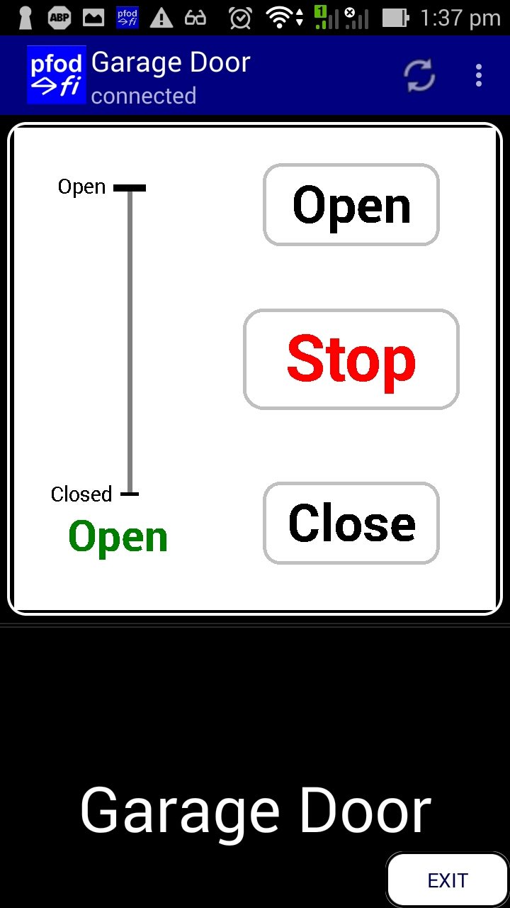
On connecting you will see a screen like this one
Press the OPEN button to open the door. You can stop the door mid way using the Stop button. The vertical gauge shows the position of the door.
For the long range radio/LoRa in-car remote control see this project.
AndroidTM is a trademark of Google Inc. For use of the Arduino name see http://arduino.cc/en/Main/FAQ
The General Purpose Android/Arduino Control App.
pfodDevice™ and pfodApp™ are trade marks of Forward Computing and Control Pty. Ltd.

Contact Forward Computing and Control by
©Copyright 1996-2024 Forward Computing and Control Pty. Ltd.
ACN 003 669 994