
|
Home
| pfodApps/pfodDevices
| WebStringTemplates
| Java/J2EE
| Unix
| Torches
| Superannuation
|
| About
Us
|
|
|
AC Power/Light Switch Monitor
|
by Matthew Ford 19th August 2017
©
Forward Computing and Control Pty. Ltd. NSW Australia
All rights
reserved.
This page describes a simple monitor circuit you can attach directly across a power or light switch and feed the optically isolated output to a micro-processor to tell if the switch is on or off. The circuit consumes less than 60mW of power from the AC line when the switch is open and zero power when the switch is closed. It can be modified to use less AC power if needed. The low voltage, microprocessor, side uses <0.1mA at 3.3V Vcc when the switch is open and nano amps when the switch is closed.
Safety
Warning – This circuit uses Main Voltage and is ONLY for
EXPERIENCED constructors .
110V/240V Mains power is lethal. Any
wiring to the mains power should only be done by a qualified
electrician.
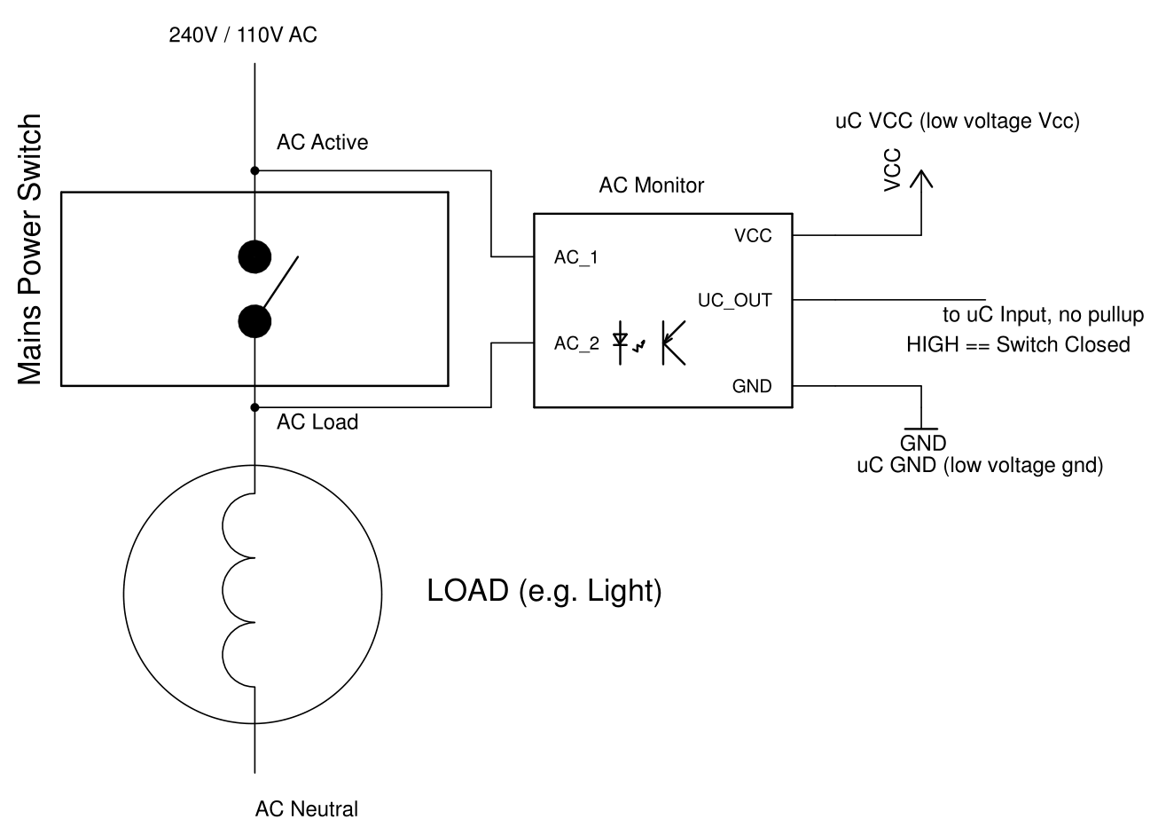
The AC Monitor is connected directly across the switch being monitored, as shown above. When the switch is open a small current (~7.5mA) flows through the monitor and uC output is driven LOW. When the switch is closed the monitor's inputs are shorted out and the uC output goes HIGH.
The monitor is 'fail safe' in that it will output HIGH (switch closed == AC flowing) if any of its input leads are broken or if the load is disconnected. To protect against a break in the lead to the uC, the AC Monitor internal pullup resistor (R1 below) can be moved to the input of the uC.
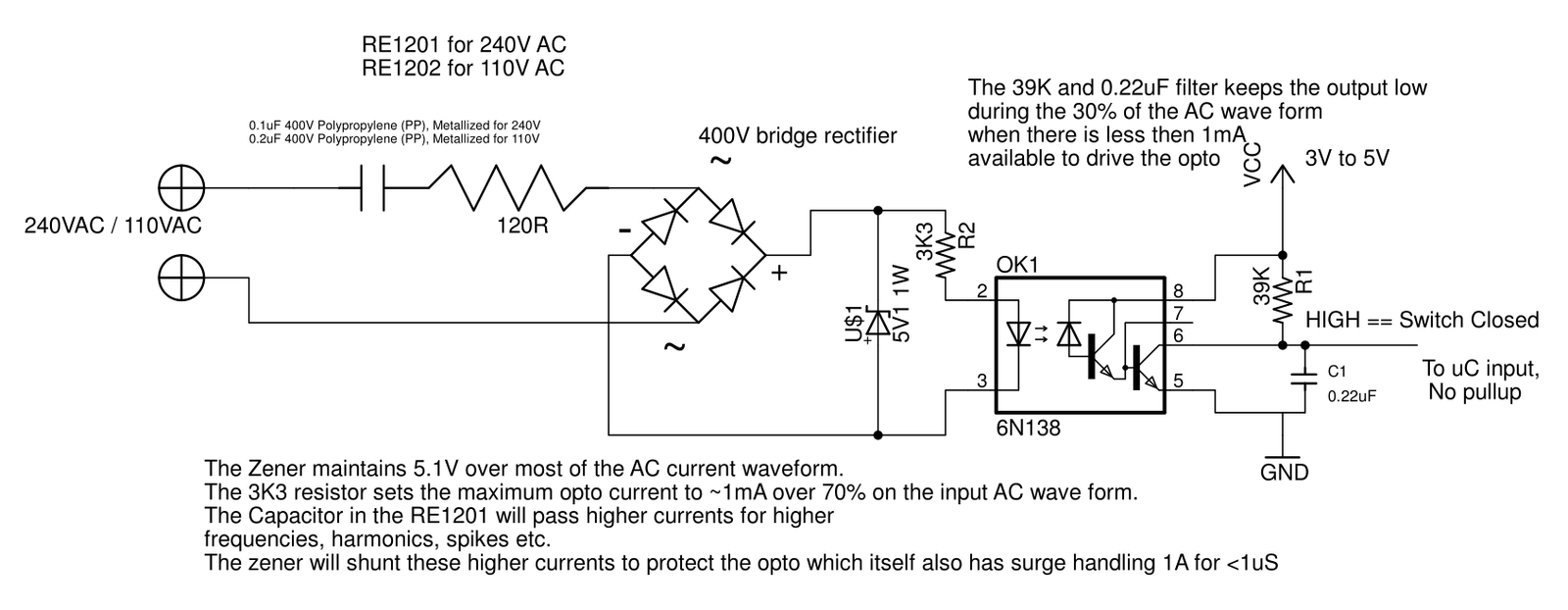
Click image to download
schematic pdf.
The circuit use a commercial relay contact snubber, RE1201 (RE1202 for 110V) to limit the current through the 5.1V zener to about 7.5mA. If you have trouble sourcing the RExxxx components you can make your own from a 120Ohm 1/2W resistor in series with a 0.1uF 400V metallized polypropylene capacitor (0.2uF 400V for 110V AC). The bridge rectifier can be any 400V device.
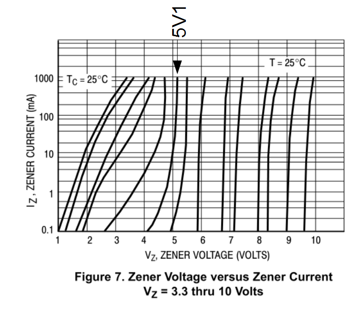
The 5.1V 1W zener provides protection against power spikes and harmonics. A 5.1V zener is used because lower voltage zeners do not regulate the voltage well at low currents, see the diagram below. Even the 5.1V zener drops to 4.2V at 0.1mA
The 39K (R1) output pullup combined with the 0.22uF (C1) capacitor holds the output LOW during those parts of the AC cycle when the current is not sufficient to drive the opto.
This circuit consumes less than 60mW of power from the AC line when the switch is open and zero power when the switch is closed. You can reduce the power consumed by reducing the size of the AC snubber capacitor. For example for 240V a 120R resistor and 0.47uF 400V (0.1uF 400V for 110V) capacitor will use about 30mW of power. If reduce the AC snubber capacitor, you will need to increase the size of C1, to say 0.47uF, to hold the output low when there is insufficient AC current to drive the opto.
AndroidTM is a trademark of Google Inc. For use of the Arduino name see http://arduino.cc/en/Main/FAQ
The General Purpose Android/Arduino Control App.
pfodDevice™ and pfodApp™ are trade marks of Forward Computing and Control Pty. Ltd.

Contact Forward Computing and Control by
©Copyright 1996-2020 Forward Computing and Control Pty. Ltd.
ACN 003 669 994