
|
Home
| pfodApps/pfodDevices
| WebStringTemplates
| Java/J2EE
| Unix
| Torches
| Superannuation
| CRPS Treatment
|
| About
Us
|
|
|
ESP-01 Timer Switch
|
by Matthew Ford 5th
May 2024 (originally posted 29th December 2021)
©
Forward Computing and Control Pty. Ltd. NSW Australia
All rights
reserved.


Update 28th
May 2024 – Added Water
Pump Control application
Update 5th
May 2024 – Added
libraries.zip and ESP8266LittleFS-2.6.0.zip files
Update
6th August 2022 – See
https://github.com/nayarsystems/posix_tz_db/blob/master/zones.csv
for a list of time zones and their posix_tz strings used in this
project
Update 11th Jan 2022 –
Added DHCP server to AccessPoint used to set network settings. V1.1.0
Parts List
Day
to Day Operation
Connecting the ESP8266
Power Timer to your local WiFi network
Forcing
Network re-configuration
Creating the QR
codes
Setting the Power Timer's Time
Zone and Daylight Saving Time (dst)
Updating
TZ.h to the latest version of Time Zones
Updating
the TimeZone/dst on a completed Power Timer
Updating
the Time Zone by setting the Time
Updating
the Time Zone by setting the POSIX string
Building
the Relay Module – Preventing Relay Flicker on
startup
Programming the ESP-01S or
ESP-01
Setting the Blue
Led Pin
Setting the TZ
and WiFi defaults
Compile
and Upload the Sketch and Data
Modifications
to the Relay Module
Possible Extensions
This project allows you to turn power on/off at specific times during the day. The times are kept accurately over years (with in a second) using NTP adjusted for the local time zone and daylight saving (dst). You can un-plug it and it will retain its settings and re-sync to the correct time when you plug it in again. It is easy to control via a webpage and if it is ever moved to another location, it is easily re-configured to the new network and the new time zone/dst without re-programming. This project has a lot of sections, but when you are finished the Day to Day Operation is all you need.
It is based on an inexpensive ESP-01S or ESP-01 module matched with a relay/power supply module. Cost ~US$14 (plus shipping and $6 programming module). This project is suitable for beginners provided you are only switching DC voltages up to 30V. This project also covers preventing relay flicker on power up. This project also covers creating QR codes for URL's and WiFi networks. The code includes files for setting the WiFi configuration, handling NTP, working with LittleFS file system and parsing and cleaning up POSIX time zone strings. Check out the .html and .css files in the ESP2866_power_timer.zip data sub-directory for web code for a ticking clock that is independent of the browser's clock, for a page refresh on focus and for popup help.
ESP8266
ESP 01S 5V WiFi Relay Module – US$6 Note: This includes the
ESP-01S module and there is a cheap shipping option. The default code
expects an ESP-01S If you use an ESP-01, you need to change
the ESP_LED define at the top of ESP8266_power_timer.ino sketch
5V
USB supply and cable – ~US$3 to ~US$8 from various sources,
e.g. Wall
Adapter Power Supply - 5.1V DC 2.5A from sparkfun. The one used
in this project is 5V
DC 1A Ultra-Slim Power Supply – MP3144 from Jaycar
1000uF
>6.3V capacitor – e.g Jaycar
1000uF 10V US$0.5
Small Plastic box – ~US$2.50 e.g.
Jaycar
HB6004. The one used in this project is the stronger version
Jaycar
HB6120
Arduino
IDE and the ESP8266
V3.0.2 add on installed via the IDE board manager. This project
used ESP8266 V3.0.2. Other versions will their own set of
features/bugs.
ESP2866_power_timer.zip
and libraries.zip –
The source code also needs the following libraries to be
installed via the Arduino IDE Library Manager:- SafeString
V4.1.14+, ESP Async WebServer V1.2.3 and ESP AsyncTCP V1.2.2
libraries.zip contains
those files. Unzip to your Sketch
directory.
ESP8266LittleFS-2.6.0.zip
– This tool is needed to upload the web site data files. See
https://github.com/earlephilhower/arduino-esp8266littlefs-plugin/releases
Total cost, as at Dec 2021, excluding shipping and a
programming module – ~US$14 to ~US$19.
In
addition to the components you need some means of programming the
ESP-01S. There are various
ways to do this. This project use a
serial Adaptor with break out pins, ESP Link V1.0 (~US$6) as
described below under Programming the
ESP-01
For Programming an ESP
Link V1.0 Programming module ~US$6 (or less), a 330R resistor
(~US$1.0 e.g SparkFun
or Jaycar)
and a female-female jumper cable, e.g. Sparkfun
PRT-08430 ~US$4 for 10 leads
The ESP Link V1.0 needs a CP2104
Driver which can be downloaded from Silabs
VCP driver (windows/mac/linux)
Since this project was mounted in an opaque ABS
box 2 leds/resistors were fitted to the lid to show the status of the
Power Timer
2 Leds different colours – e.g. Sparkfun
Assorted Red + Yellow US$0.75
2 x 330R resistors – e.g.
SparkFun
or Jaycar
~US$1.00 pk
In day to day
operation you will want to be able to change the mode of operation,
Off, On or Auto and to set the On and Off times (used when in
Auto)
(How to connect the
Power Timer to your local network and how to set your time zone will
be covered later, but usually not needed)
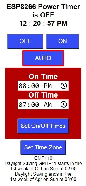
The mode and On/Off times are set via a web
page. Scan the QR code to connect your browser to the ESP8266 Power
Timer main page. The IP is set as part of the setup (see later). See
below for how to create this QR code for your own
IP.
That page lets you turn the power On or Off or set to Auto
so that the On/Off times control the power. To change On/Off times
edit the times and then click on the Set On/Off Times button.
If you happen to watching just as timer turns off, you will see the blue ESP-01 led flashing as the ESP-01 reconnects. Each time the timer turns off (in Auto) the ESP-01 reboots to clean up any memory leaks. This ensures the software will run for years without locking up. If the Timer is OFF, then is reboots once each 24hrs. If the Timer is ON it does not reboot.
That's all there is to it!
If you set your network SSID and pw and a static IP
in the sketch before programming you will not need to do this, but if
you move house you may need to connect to a new network.
When you
load the program into the ESP-01S you can set a default WiFi network
SSID and password, so it will just connect without further network
setup. (see below for how to force a re-configuration)
Near the top of the wifiConfig.cpp file you will find
#define wifiSSID ""
#define wifPassword ""
#define wifiStaticIP "10.1.1.212"
Update these with your home network's SSID and password and choose a static IP for this Time Switch.
NOTE: The staticIP must be in the range covered
by your router and must not be in use by another device.
Typical
local network ips are 10.1.1.xxx, 172.16.0.xxx and 192.168.0.xxx
You
can use an app to see which one your network uses and what other
devices are on the the network. I used Angry
IP Scanner
Important:: You must
choose a static IP in your network's range. An IP of 10.1.1.212 will
not work if your home network uses 192.168.0.xxx etc.
Once you have coded these default settings the Power Time should just connect to your network when you plug it in.
If it does not connect you will see the ESP-01S Blue led flash rapidly (5 times a second) for 30 sec as it tries to connect and then start to flash slowly (1sec on 1sec off) indicating the Power Timer is in network setup mode. In network setup mode the Power Timer creates a temporary Access Point (network), for 5 mins, that you can connect to to set your network's SSID, password and the static IP. At the top of wifiConfig.cpp you will find the default Access Point SSID and password
#define wifiWebConfigPASSWORD "12345678"
#define wifiWebConfigAP "PwrTmr"
This QR code will connect you to that network. See below for how to create you own QR code if you want to have a different configuration SSID and pw. If you want to use this default one you can print out this pdf file.
Note: The Access point (router) always uses the 10.1.1.1 private
network address regardless of what your home router uses.
Note:
When in Access Point mode, a DHCP server on the ESP8266 provides an
IP for your computer/mobile. Set your computer/mobile to get it IP
via DHCP (this is the usual setting). If you have set a static IP on
your computer, if it is not in the 10.1.1.xxx range it will not
connect to the PwrTmr access point. Change your computer to use DHCP
instead while doing this network setup.
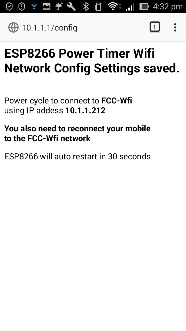
When you connect your mobile to this temporary access point and use your browser to open http://10.1.1.1 you will see this configuration web page
The SSID will be filled in with nearest network. Fill in the SSID, password and choose a free ip on your home network and click on Config to display this result webpage. The Power Timer will reboot in 30sec and try to connect the the configured network.
So to summarise. In order to display the ESP8266 Power Timer Wifi Network Config Setup webpage above, you should set your computer/mobile for DHCP. BUT when you fill in the Static IP field in that webpage, you need to choose an unused IP from your router's network,
The network configuration temporary access point will not be started unless the Power Timer fails to connect to a network, so to force the Power Timer into configuration mode, turn off the router it is connecting to. You usually don't need to do this except if you need to change the configured IP for the Power Timer. Normally if you move the Power Timer to a new location, it will just try to connect for 30 secs (fast flashing) and automatically switch to network configuration (slow flashing) and start the temporary access point.
This project uses two QR codes. The 'front' one contains the URL to the Power Timer main page to set the mode and on/off times. The 'back' one contains the WiFi network details for the temporary access point the Power Timer sets up if it cannot connect to your network. There are many sites that offer to create these QR codes. This one https://qr-code-generator.org seems to be a simple one uncluttered by adds.
To create the URL link, choose Link type and type in http:// and the ip you set for your Power Timer, e.g. http://10.1.1.212 Then choose a Frame and add http://10.1.1.212 as the text. Finally save the QR code and drop it into a drawing program, like OpenOffice Draw, to add other text.
To create the WiFi network setting, choose the WiFi type and enter the SSID and password. Choose WPA/WPA2 for Network Type. Chose a frame and add the WiFi details so that users can still connect without needing to scan the QR code.
Before you program the ESP-01, you can set your local timezone/daylight saving. At the top of ESP8266_power_timer.ino you will see
#include <TZ.h>  // for list of pre-generated TZ POSIX strings
// set a compiled default TZ here. Can be overrided/edited later by webpage.
#define DEFAULT_TZ TZ_Australia_Sydney
You can set the DEFAULT_TZ to one of those listed in the ESP8266 TZ.h file (local example of that file here). The ESP8266 TZ.h file is located in ..... Arduino15\packages\esp8266\hardware\esp8266\3.0.2\cores\esp8266\TZ.h
Time zones and daylight savings are at the whim of politicians and so can change for no good reason. On Linux/Mac computers, see the instructions at the top of the ESP8266 TZ.h file for how to update it with the latest values. On windows machines you can use the following process.
Install cygwin from https://www.cygwin.com/
run setup-x86_64.exe
downloads from internet
installs to dir C:\cygwin64
just click Next
Then go back and install curl which is also needed. Search for curl
put TZupdateWin.sh in C:\cygwin64\home\<user> where <user> is the username to login with.
Start cygwin terminal and run TZupdateWin.sh and run using
./TZupdateWin.sh
then youe can either just open the resulting TZ.h file in an editor or use this command to get, for example the Sydney entry
$ grep "Sydney" ./TZ.h
#define TZ_Australia_Sydney PSTR("AEST-10AEDT,M10.1.0,M4.1.0/3")
finally copy updated TZ.h back to
.....
Arduino15\packages\esp8266\hardware\esp8266\3.0.2\cores\esp8266\TZ.h
As noted above, you can set the local timezone/dst before you program the ESP-01 so usually that is all there is to it, unless you move to a different timezone or the politicians change the rules. In that case you can update the Power Timer's timezone and dst rule without having to reprogram the ESP-01
Open the Power Timer Settings web page.
and click on the Set Time Zone button to open the TZ setting page.
Here you have the option of just setting the current time (+/- 2mins) or entering the POSIX string that describes the timezone.
If you enter the current time and click Set Time then the Power Timer will calculate the correct time zone offset from GMT without any daylight saving rules. For example
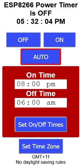
This is the simplest way to set up the Power Timer if you move to another timezone. If that time zone does not have daylight saving, then this is all you need to do. Even if it does have dst then you can still use the simple method but you will need to reset the time twice a year as dst starts and stop, just as you need to for mechanical clocks.
If the zone you have moved to has daylight saving rules you can
enter the appropriate POSIX string (copied from TZ.h for example) to
set the dst rules.
See
https://github.com/nayarsystems/posix_tz_db/blob/master/zones.csv
for a list of time zones and their posix_tz strings that can be
copied into this project.
See Explanation of TZ strings (local copy here) for how this string is constructed. When you click Set TZ Format the input string is parsed and cleaned up and if the cleaned up string is different from what you entered then it is re-displayed for your approval or further corrections.
Once the input string equals the parsed/cleaned up string, that TZ is accepted as valid and the Power Timer returns to the main page.
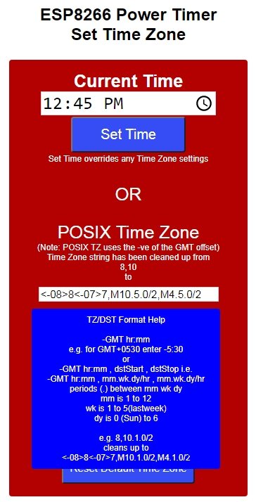
The parser is a simple one and can be easily confused by invalid
formats. At a minimum you need to specify the number of hours:mins to
add to your timezone to get back to GMT. e.g.
-10 for GMT+10
5:30
for GMT-0530 The : in the POSIX string is important.
Next if your timezone has daylight saving then you need to add a comma and specify the start of dst month . week . dayOfWeek and optionally /hr which defaults to 2am if missing. This is followed by a , and when the details of when dst ends. The parser/cleanup will fill in defaults for the week (5 == last week in the month) and dayOfWeek (0 == Sunday) if missing, and if the end of dst section is missing it will default to 6 months later. The default dst shift is 1hr.
E.g. entering
8,10
will be parsed and cleaned up to
<-08>8<-07>7,M10.1.0/2,M4.1.0/2
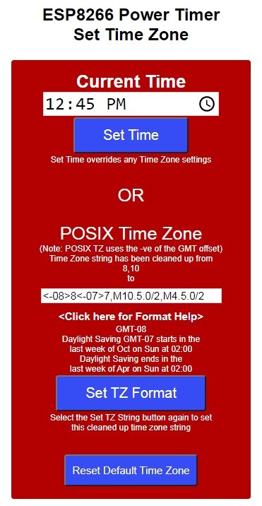
There is popup help for the time zone format <Click here for Format Help>
Finally there is Reset Default Time Zone to restore the time zone setting that was programmed into the ESP-01 as its default.
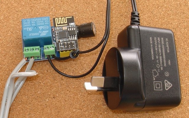
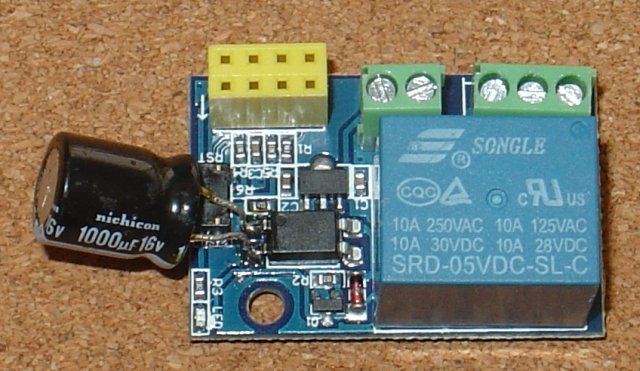
The relay module is pre-built so there is not much to do other than, add the 1000uF capacitor, plugging in the programmed ESP8266, wiring up the 5V supply and wiring in the power line you want to control.
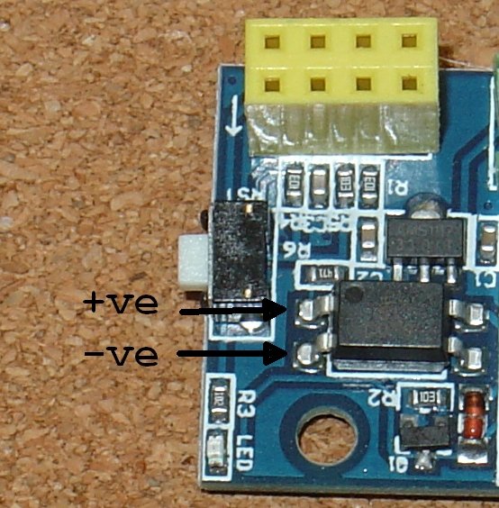
When the ESP-01 (actually any ESP8266) starts up, it toggles GPIO0 for a short time. This is enough to trigger the relay for a short time. To prevent this relay flicker on startup as large (1000uF) capacitor is added across the optical isolator inputs.
First add the capacitor 1000uF 6.3V (or higher voltage) across pins 1 and 2 of the opto-isolator. Note carefully the polarity of the capacitor and match to the pins as shown below.
The schematic for the Relay Module V4 is here.
Then wire in the 5V supply and the low voltage (<30 dc) power lead you want to control. Note: Carefully check which lead is the +5V lead. that lead goes to the VCC terminal. Otherwise you will damage the module. Here the +ve has had a knot added to it to make it easy to identify. For the power lead you want to control just cut one of the pair and strip the ends and insert in the COM and NO terminals.

That is the construction complete. You can put it in a clear plastic box so the ESP-01S and Relay module leds are visible and attach the QR codes. In this project, the relay module was mounted in an opaque box so extra leds/resistors had to be added. They were soldered to the bottom of the relay board so the ESP-01S module could still be easily removed for programming.

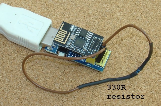
An inexpensive serial Adaptor with break out pins, ESP Link V1.0 was used to program and test the ESP-01S. To program, link the GPIO0 and GND pins with a jumper lead and a 330R resistor. The resistor value is low enough to initiate programming when the reset push button is pressed, but not so low as to short out any ESP8266 output if it is plugged into the wrong pins. In the Power Timer, GPIO0 is used to drive the relay and is normally driven HIGH to turn the relay OFF on startup. The 330R resistor limits the GPIO0 pin current to 10mA if it is driven HIGH, so you can safely plug in the jumper while the sketch is running and then just press the reset push button to get into programming mode.
To program the ESP-01S or ESP-01, install
the ESP8266 Arduino IDE add on V3.0.2. Other versions of the
ESP8266 code will have their own set of bugs/features. The Power Time
code has been developed and tested using V3.0.2.
The ESP Link V1.0
requires a CP2104 driver. If it is not automatically found you can
install it from Silabs
VCP driver (windows/mac/linux)
Unzip the ESP2866_power_timer.zip
file to your Arduino sketch directory. You also need to install the
following libraries using the Arduino Library Manager:- SafeString
V4.1.14+, ESP Async WebServer V1.2.3 and ESP AsyncTCP
V1.2.2.
libraries.zip
contains these libraries. Unzip to your Sketch directory.
You also need to install the ESP8266 LittleFS
data uploader.
1) Download ESP8266LittleFS-2.6.0.zip from
https://github.com/earlephilhower/arduino-esp8266littlefs-plugin/releases.
(local copy
here)
2) In your Arduino Sketch directory create a tools
subdirectory (if there is not already one) and
unzip ESP8266LittleFS-2.6.0.zip to that tools
subdirectory.
3) You should end up with a file
called esp8266littlefs.jar in
a directory ...\Arduino\tools\ESP8266LittleFS\tool
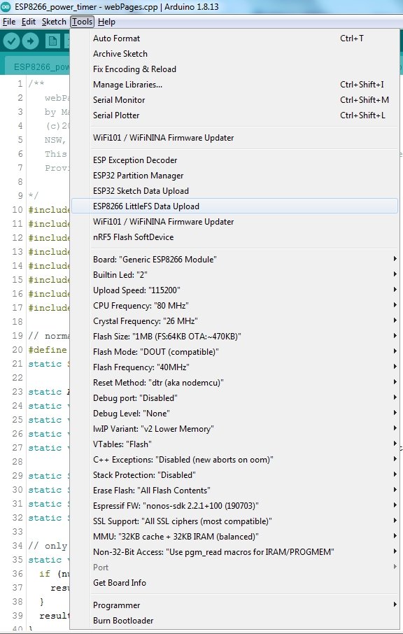
4)
Stop and restart the Arduino IDE and you should see under Tools menu
the ESP8266 LittleFS Data Upload.
Also in this menu, select
Generic ESP8266 Module as the board and towards the bottom of the
menu, under “Erase Flash” select “All Flash
Contents”
The “Flash Size” should be set to
1MB(FS:64K OTA~470KB) The Power Timer only uses FS not OTA.
Open the ESP8266_power_timer sketch. It contains ESP8266_power_timer.ino and a number of supporting .cpp and .h files.
The default code in ESP8266_power_timer.ino is for an ESP-01S module, which drives the Blue led via GPIO2, and has near the top of the file
// for ESP-01S
#define ESP_LED 2
If you are using an ESP-01 module which has the Blue led driven by TX (GPIO1), and which also has a Red power led in addition to the Blue led, then change this define to
// for ESP-01
#define ESP_LED 1
On the ESP-01, if you are debugging, the Blue led will not flash, only flicker as debug msgs are written. Commenting out #define DEBUG will restore the Blue led flashing.
At the top of the ESP8266_power_timer.ino you can specify your default time zone
#include <TZ.h>  // for list of pre-generated TZ POSIX strings
// set a compiled default TZ here. Can be overrided/edited later by webpage.
#define DEFAULT_TZ TZ_Australia_Sydney
Open the ..... Arduino15\packages\esp8266\hardware\esp8266\3.0.2\cores\esp8266\TZ.h file to see what time zone names the ESP8266 recognizes (a local copy is here). You can override this later via a webpage if needed.
At the top of the wifiConfig.cpp file you can specify your wifi network's SSID and password and the static IP you want to use for the Power Timer
// replace these with your network's SSID and password and the static IP you want for this Power Timer web server.
#define wifiSSID "yourSSID_here"
#define wifPassword "yourPW_here"
#define wifiStaticIP "10.1.1.212"
// 10.1.1.212 is an example
// NOTE: choose an IP on your network!!To program
the ESP8266, insert the 330R link between the GND and GPIO0 breakout
pins of the serial
adaptor and press the reset push button and compile and upload
the sketch. This takes some time.
Then to upload the html files in
the /data subdirectory of the ESP8266_power_timer directory, press
the reset push button again and then choose Tools → ESP8266
LittleFS Data Upload. This is much quicker.
Remember
to close the Arduino Serial Monitor if it is open, before using
ESP8266 LittleFS Data Upload, otherwise the upload can fail.
Finally remove the ESP8266 and plug it into the Relay module and turn on the 5V supply. The blue led should flash quickly for a few seconds and then go on solid. You can then open a web page at the IP you chose, e.g. http://10.1.1.212 and set the Power Timer mode and On/Off times.
If the Power Timer cannot connect, after 30 seconds the blue led will flash slowly and the temporary access point will be setup for you to correct your WiFi SSID and password. See Connecting the ESP8266 Power Timer to your local WiFi network.
The relay module has a 5V Relay rated for 240V 10A, but the screw connectors will not accept heavy duty power cable and one relay contact PCB tracks is unnecessarily close to the GND pin. So this module is not recommended for mains power use. For low voltage use, <30VDC, there is another possible problem. The relay has a 5V coil, but Version 4.0 of the relay module uses the 3V3 supply to drive the relay (V1 previously used VCC). While the two modules tested both worked as is, this low coil voltage seems marginal.
With few modifications, shown below, relay can be drive from the VCC (5V) supply. The diode added is a 1N4001 or similar. The orange diode removed is the previous 'flywheel' diode. It is important to remove this orange diode.
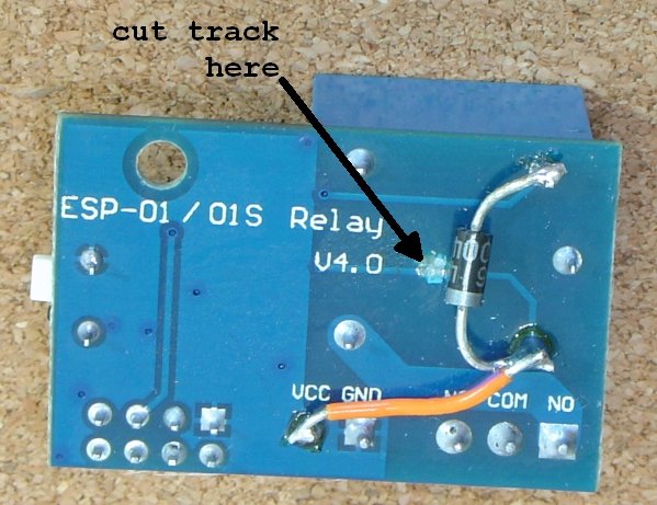
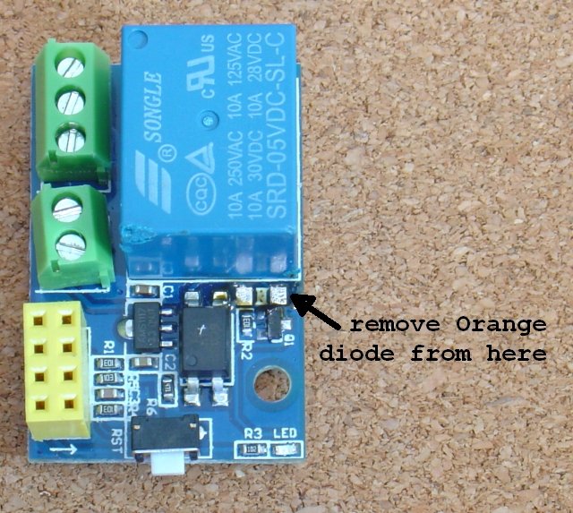
So if you find that the relay does not always pick up (turn on), the try the above modifications.
There are at least two extensions you could make to this
project.
1) Allow for multiple on/off periods within the 24hrs,
instead of just the one currently implemented. This requires extra
data structures and web page modifications.
2) Add a day of week
setting to the on/off periods so that they only operate on specified
days of the week. In addition to the extra data structures and web
page modifications, this requires removing setting the time zone by
setting the time.
Currently if the time zone is set by setting the
time (instead of the POSIX string), for time zones outside GMT+/-12,
like New Zealand, the day of the week will not be correct. So time
zone needs to set via the POSIX string to get the correct day of the
week.
The project proves a simple accurate 24hr power timer for low voltage (<30VDC) use. The on/off times and the mode (On/Off/Auto) can be changed via a web page whose URL is displayed via a QR code. It keeps accurate time via NTP and include Time Zone and Daylight saving adjustments. You can un-plug it and it will retain its settings and re-sync to the correct time when you plug it in again. If you move houses, you can easily connect to the new network using the WiFi config webpage, without reprogramming and also set the new Time Zone / DST without reprogramming.
AndroidTM is a trademark of Google Inc. For use of the Arduino name see http://arduino.cc/en/Main/FAQ
The General Purpose Android/Arduino Control App.
pfodDevice™ and pfodApp™ are trade marks of Forward Computing and Control Pty. Ltd.

Contact Forward Computing and Control by
©Copyright 1996-2024 Forward Computing and Control Pty. Ltd.
ACN 003 669 994