
|
Home
| pfodApps/pfodDevices
| WebStringTemplates
| Java/J2EE
| Unix
| Torches
| Superannuation
|
| About
Us
|
|
|
pfodGUIDesigner App
|
by Matthew Ford 7th March 2023
(originally posted 30th
Sept 2022)
© Forward Computing and Control
Pty. Ltd. NSW Australia
All rights reserved.
Update 14th
Jan 2023 – installing ESP32
V2.0.6 board support seems to fix the previous problems with
Adafruit
QT Py ESP32-C3)
Update
1st
Dec 2022:
pfodGUIdesigner
Android app released which replaces the previous Arduino
code version.
Note about Underlines: pfod allows you to specify underline for text labels, however some Android mobiles, e.g. Lenove tablet, always display the underline left adjusted regardless of the label alignment (left,center,right). Other mobiles work correctly. The 'fix' is to set the labels to be Left adjusted (default is center).
This page covers using the free pfodGUIdesigner Andriod app to design your own custom Arduino Graphical User Interface (GUI) components for Arduino/pfodApp and generate the Arduino class code that implements them. The final components are very light weight and can easily run on an UNO or better board, connected to a communication shield. The generated code is saved to a file on your mobile to be download. The pfodApp operates like a micro browser. It takes its instructions from your Arduino sketch, via compact text messages and displays a hierarchical menu of buttons, sliders and drawings, as well as chart, text and numeric input screens as requested by the messages sent by the sketch. The current version of pfodApp runs on Android mobiles from V4.4 onwards, so you can repurpose your 8 year old mobile as an dedicated Arduino interface.
A number GUI component design examples are given:- a Relative Humidity Gauge, a Push Button (with immediate user feedback), an OnOffSlider (with immediate feedback), a Text Input/Edit example and a temperature gauge. The generated code classes for these components are then combined in to a user interface by simply scaling and positioning the components.
Short (silent) videos are provided for each design.
All the pfodGUIdesigner's displays are drawn using the pfod dwg cmds (see previous Ardino code version for details of the underlying pfod dwg cmds). The pfodGUIdesigner consists of an instance of pfodApp permanently linked to the backend drawing and code generator. This gives a WYSIWYG (what-you-see-is-what-you-get) designer. Because the link to the GUI designer's backend is a fixed connection, you need to purchase the general purpose pfodApp to use the designed GUI when it is served by an Arduino board.
The pfodGUIdesigner generates class files for the designed component together with some test code to run in a variety of Arduino boards, ESP32 Wifi, BLE and Bluetooth, ESP32C3 Wifi, ESP8266 Wifi and Nano 33 IOT and BLE and Serial connections for Uno/Mega connected to a communication shield, e.g. Cheap/Simple WiFi Shield. For other boards use the free pfodDesignerV3 to generate connection code for a much wider variety of boards including SMS connections. The GUI component generated class files are the same for all target boards.
There is also a separate tutorial on how to create complex GUI's by adding separately designed GUI components.
Watch the short (silent) videos about using the pfodGUIdesigner sketch.
Install the free pfodGUIdesigner Android app.
Create your GUI design and generate the Arduino code that implements it.
Download and paste the generated code into a new sketch, set your network ssid/password and program your Arduino board.
Install the pfodApp on your Android mobile (V4.4+) and create a connection to your staticIP port 4989. See pfodAppForAndroidGettingStarted.pdf
Connect with pfodApp to test your GUI component design.
Split out the .cpp and .h code sections into separate files to get reusable classes.
Any Arduino board with WiFi, BLE, Bluetooth or
SMS connection, e.g. ESP8266, Nano 33 IOT, Nano 33 BLE, ESP32 etc.
and a wide variety of other boards. Here an ESP32-C3
~ US$10 was used (
Update 14th
Jan 2023 – installing ESP32 V2.0.6 board
support seems to fix the previous problems with Adafruit
QT Py ESP32-C3 note
Adafruit's mini Adafruit QT Py ESP32-C3 does not work).
Note also: ESP32 boards e.g. Sparkfun ESP32 Thing, take two or three
auto re-connects from pfodApp establish a connection after a power
cycle/re-program. Runs fine after that. This is a know problem for
V2.0.0+ versions of the ESP32 Arduino board software.
pfodParser
V3.61.0+ and supporting libraries SafeString
pfodApp
~ US$12
Any Android mobile from the last 8 years, i.e. Android
V4.4+. So you can repurpose that old Android phone as a dedicated
Arduino controller/interface.
An Arduino board for your final
project with a WiFi, Bluetoot, BLE or SMS connection.
Above are the basic drawing controls. You can edit the position and size in the element's properties panel that is displayed below the drawing panel. You can also drag the current element round. At the heart of the pfodGUIdesigner is a drawing package built using the basic pfodApp dwg commands (see the pfodSpecification.pdf).
When dragging the element it is positioned above your finger so you can see where it will be positioned. This positioning offset is not built into pfodApp but programmed in the Arduino code by adding a pushZero()/popZero() pair of statements. The following video (basicControlsVideo.mp4 00:03:20) shows the function of the basic drawing controls. The popup text edit dialog box to edit the element's size, position etc, is also completely controlled by the Arduino sketch code, which specifies when it should be shown, what color it should be, what the prompt is and which element the default text is sourced from.
The basic dwg elements are rectangles, lines, circles, arcs, labels, touchZones and touchActions/Inputs (dialog text edit box). Not all the options available for these elements are covered by the designer. See the pfodSpecification.pdf for all the details and the other supporting commands like pushZero()/popZero(), hide()/unhide() and insertDwg(). The pfodGUIdesigner itself uses these elements to create its own interface, so check out the pfodGUIdesigner sketch files for examples of advanced usage. These low level elements that can be combined to create sophisticated GUIs.
Note carefully the use of the Show (S) button, to show the current drawing element. You will use this often to confirm which element you are working on. When editing the basic dwg elements, rectangles, line, circle, arc and label, the (S) button flashes the element currently being edited. For touchZones, the (S) button simulates a user touch of that zone and triggers any actions defined. For touchActions, the displayed element is the action replacement element being edited and the (S) toggles between it and the dwg element that it is replacing. For touchActionInputs, (S) displays the text input dialog box so you can visually check the property settings. The later examples will illustrate these uses of (S)
 (basicControlsVideo.mp4
00:03:20)
(basicControlsVideo.mp4
00:03:20)
There is no save option, all the edits are automagically saved. In the pfodGUIdesigner app the edits are automatically saved in the app private file space as they happen and are there next time you open the app.
SaveAs copies the dwg to a new name. Deleting a dwg requires you to first delete all the elements, before deleting the empty dwg itself. The pfodGUIdesigner sketch allows for up to 15 dwgs at a time.
In the previous Arduino Code version they were saved to non-volatile flash on the ESP, so they are there when you next power up the ESP micro. Check out the Arduino code of the Arduino Code version for how the edits are saved in the files. The files survive reprogramming the ESP with the generated code test sketches, so you could test the generated code and then reprogramming the pfodGUIdesigner sketch and continue editing.
This Android App version of pfodGUIdesigner supports generating test code for a wide variety of Target boards using Serial connections (Uno/Mega + Serial WifiShield), Wifi (ESP32, ESP8266, ESP32C3, Nano 33 IOT), BLE (generic nRF52832, Nano 33 BLE, Nano 33 IOT and ESP32 and ESP32C3 via BLE, Adafruit Bluefruit Feather52 and LE Flora and UART Friend and Bluefruit LE SPI) and Bluetooth Classic (ESP32)
The examples here all use the ESP32C3 via Wifi target. You can
choose another target board by selecting the Change Target
option after you select Generate Code.
In
all cases the GUI component class files generated are the same for
ALL targets. Only the test code setup/loop changes to suit the
target, The free pfodDesignerV3 Android app generates setup/loop code
for a much wider variety of targets and you can easily reuse the GUI
component classes, unchanged, on those boards as well
 (Final RH_Gauge component in operation,
finalRH_GaugeDemo.mp4
00:00:50)
(Final RH_Gauge component in operation,
finalRH_GaugeDemo.mp4
00:00:50)
This example designs a Relative Humidity Gauge similar to the ones used on the Weather Station project. Once you have drawn the gauge and generated to Arduino code, the example will cover updating the gauge with the current reading.
Tip: Although you can scale your GUI components after they
are completed, design your GUI components at about final size so you
can check the labels are easily readable.
Tip: On some mobiles, if
the element's properties panel does not look like it has updated,
move the phone's vertical slider a fraction to force Android to
redraw the screen.
The first video (RH_Gauge_1.mp4 00:05:00) covers placing all the constant elements for the RH Gauge.
 (RH_Gauge_1.mp4
00:05:00)
(RH_Gauge_1.mp4
00:05:00)
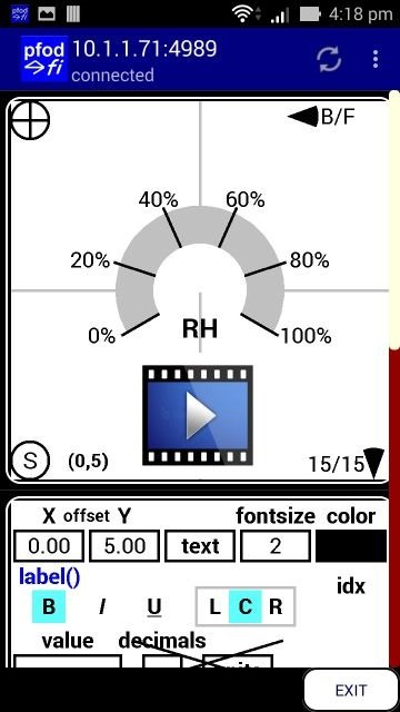
Here are the elements and their properties (from the generated code)
dwgs.arc().color(7).offset(0.00,0.00).radius(11.00).start(210.00).angle(-240.00).filled().send();dwgs.arc().color(0).offset(0.00,0.00).radius(12.00).start(210.00).angle(0.00).send();dwgs.arc().color(0).offset(0.00,0.00).radius(12.00).start(162.00).angle(0.00).send();dwgs.arc().color(0).offset(0.00,0.00).radius(12.00).start(114.00).angle(0.00).send();dwgs.arc().color(0).offset(0.00,0.00).radius(12.00).start(66.00).angle(0.00).send();dwgs.arc().color(0).offset(0.00,0.00).radius(12.00).start(18.00).angle(0.00).send();dwgs.arc().color(0).offset(0.00,0.00).radius(12.00).start(-30.00).angle(0.00).send();dwgs.label().color(0).offset(-13.00,6.00).fontSize(0).center().value(0.000000).decimals(0).units("%").send();dwgs.label().color(0).offset(-14.50,-4.00).fontSize(0).center().value(20.000000).decimals(0).units("%").send();dwgs.label().color(0).offset(-5.50,-12.00).fontSize(0).center().value(40.000000).decimals(0).units("%").send();dwgs.label().color(0).offset(6.00,-12.00).fontSize(0).center().value(60.000000).decimals(0).units("%").send();dwgs.label().color(0).offset(14.50,-4.00).fontSize(0).center().value(80.000000).decimals(0).units("%").send();dwgs.label().color(0).offset(14.00,6.00).fontSize(0).center().value(100.000000).decimals(0).units("%").send();dwgs.arc().color(15).offset(0.00,0.00).radius(6.00).start(210.00).angle(-240.00).filled().send();dwgs.label().color(0).offset(0.00,5.00).text("RH").fontSize(2).bold().center().send();
Having placed the static elements, the gauge value and indications need to be added. These three elements, the value label, the red gauge arc and the black marker line need to updated with the current RH value.
pfodApp uses indices to uniquely identify dwg elements so they can the update/replaced. Indices also determine the layering order. Elements without indices are drawn in the order received. Elements with indices are then drawn on top in order of their index from lowest to highest. The indices need not be sequential. While you can manually assign uint16_t numbers for indices, the generated code uses pfodAutoIdx objects which allocate globally unique indices sequentially as they are first sent to the pfodApp. The name of the pfodAutoIdx variable has no relation to the actual index.
In pfodGUIdesigner each primitive drawing element has an
update/idx button which when highlighted indicates that the
element needs a unique index for updating. Depending on which layer
the indexed element is, other higher elements will also need to be
indexed to keep the layer ordering. pfodGUIdesigner handles this
automatically, so you should only mark the elements that you need to
update.
pfodGUIdesigner automatically marks dwg
objects/labels for update when they are referenced by a touchAction
(action) or touchActionInput (input) of a touchZone.
This second video (RH_Gauge_2.mp4 00:03:30) adds the three elements that show an example gauge value of 65%. 65% of the -240 total arc is -156 and the marker line is at the start angle (210 – 156) = 54. These elements are then marked to update. They could have also been marked as they were added. Finally the Arduino code for this gauge is generated. You can save to a file on your mobile, but the code is also dumped to the Arduino monitor so you can just copy and paste it from there.
 (RH_Gauge_2.mp4
00:03:30)
(RH_Gauge_2.mp4
00:03:30)
The generated code is here, RHGauge_a.ino Open the new sketch and replace its code with the generated code. Save the sketch as RH_Gauge. Set your network SSID / password and staticIP and upload to your ESP. This will not erase your dwg designs. Open pfodApp and connect to see your gauge design.
 (finalRH_GaugeDemo.mp4
00:00:50)
(finalRH_GaugeDemo.mp4
00:00:50)
Once you have confirmed the display, create two new files in the Arduino sketch (using the top right down arrow in the Arduino IDE display). One file for RH_Gauge.h and one for RH_Gauge.cpp. Then cut those sections of code from the main ino sketch and paste them into their respective .cpp / .h files.
Now you need to replace the 65% example reading with variables to show the actual reading. The pfodApp caches the drawing, so you only need to send the updates to display then new reading.
Here is the generated code with the values the need to updated highlighted.
void updateDwg(pfodDwgs &dwgs) {
  dwgs.arc().idx(_update_idx_17).color(9).offset(0.00,0.00).radius(11.00).start(210.00).angle(-156.00).filled().send();
  dwgs.arc().idx(_update_idx_18).color(0).offset(0.00,0.00).radius(12.00).start(54.00).angle(0.00).send();
  dwgs.label().idx(_update_idx_16).color(0).offset(0.00,0.00).fontSize(6).bold().center().value(65.000000).decimals(0).units("%").send();
}
The values that need to replace by variables are highlighted above, -156, 54 and 65.00. -156 is the red gauge arc and is calculated by -240*rh/100. The 54 is the end marker and is (210 – 240*rh/100). The 65.00 is the current RH reading. Here is the revised updateDwg method that uses the current rh value to update the gauge.
void updateDwg(pfodDwgs &dwgs) {
  int rhArc = map(rh,0,100,0,-240); // map rh to -ve angle
  dwgs.arc().idx(_update_idx_17).color(9).offset(0.00,0.00).radius(11.00).start(210.00).angle(rhArc).filled().send();
  dwgs.arc().idx(_update_idx_18).color(0).offset(0.00,0.00).radius(12.00).start(210+rhArc).angle(0.00).send();
  dwgs.label().idx(_update_idx_16).color(0).offset(0.00,0.00).fontSize(6).bold().center().value(rh).decimals(0).units("%").send();
}
Finally add a setRH(int rh) method to set the current value, and add an int rh; variable to the RH_Gauge.h file. See the RH_Gauge.h and RH_Gauge.cpp files for the modified code.
void RH_Gauge::setRH(int _rh) {
  rh = _rh;
}
The position of the gauge on the screen and its scaling are set by the pushZero( ) statement in bool sendMainDwg() method in the .ino file. For demonstration purposes the gauge will be positioned in the bottom left corner and scaled down to 65% of the design size by using
dwgs.pushZero(12.00, 40.00, 0.65); //(x,y) offset (12,40) scaleFactor 0.65Edit static unsigned long dwgRefresh = 1000; at the top of the .ino file to refresh the menu every 1000ms (1secs) to automatically pick up the latest rh reading. In a real weather station a much slower update is appropriate. Finally for demonstration purposes code has been added to increment the rh reading on every update.
See the RHGaugeClasses_a.zip sketch for these changes and the separate .cpp and .h class files
This design example is a simple button (a coloured circle) with a touchZone which sends a command when the user touches the button.
The first design just has a green filled circle, a
black circle and a touchZone centered. The touchZone is shown in
pfodGUIdesigner as concentric rounded rectangles for
editing/positioning purposes. When this control design is in actual
use, the touchZones are not visible in pfodApp unless you have
debugging turned on for that connection.
(P.S. If you turn on
debugging for the pfodGUIdesigner connection, you will see a whole
host of touchZones that are used to run the designer.)

If you generate the code for this design, (PushButton_a.ino) and test it, you will see, in the debug statements in the Arduino monitor, that it sends a command when you touch the green circle.
 Got pfodAutoCmd:_touchZone_cmd_2
     touchZone cmd _3 at (0,-1) touch type:TOUCHED
However a much better GUI design is to give the user some indication that they have initiated a command, particularly when the communication to/from the Arduino device is slow.
touchActions provide this immediate feedback to the user. The touchActions are pre-sent to pfodApp so they can be applied immediately the touchZone is triggered by the user. touchActions are very general, you can add hide/unhide drawing elements, add extra dwg elements, replace existing elements with completely different ones and have multiple touchActions triggered by one touchZone. The pfodGUIdesigner provides for the addition of up to five (5) touchActions and one (1) touchActionInput (dialog edit box) per touchZone. The touchActionInput will be covered in the next example.
To keep the pfodGUIdesigner simple, clicking on action, initially adds a touchAction that just hides an element. You then move up/down the layers to choose the element to be hidden. With the action edit panel open, the chosen element is hidden as it is selected and the Show (S) button unhides it. When the action edit panel is closed, reverting to the touchZone, then the Show button triggers the touchZone and performs what ever actions it has. The following short video shows adding an action, a hide() action, and selecting the green circle to hide, then close the action and using the Show button to trigger the touchZone.
Note: When editing actions, the display shows the action and hides/replaces the associated drawing element. For a hide() action there is nothing to show for the action, so press the Show (S) button to toggle between the action and the drawing element being hidden to make sure you are hiding the drawing element you want hidden.
Close the action properties to go back to the touchZone and then press Show (S) to see the actions in operation.
 (simpleButtonHide.mp4,
00:00:50 )
(simpleButtonHide.mp4,
00:00:50 )
Follow the video and add a hide action to hide the green circle when the touchZone pressed, then generate the code (PushButtonHide_a.ino) and test it. When you run that sketch and connect with pfodApp you will see the green circle disappears as you touch it. The Arduino serial monitor will show the command sent.


The previous Button example showed how to use a touchAction to hide an existing drawing element. In this example existing drawing elements will be replaced with different elements with different colour and at different positions, when the touchZone is triggered by the user's touch. An OnOffSlider is used to illustrate this.
Start a new drawing called OnOffSlider and create the slider in the Off position. See the first part of the video below for the how to draw the slider, up to 00:02:60. Note that the filled circle at the end of the rectangle under the large Off button is colored Green. It will be uncovered when the action moves the Off button to the left. Setting it to Green means it does not need to be updated when the slider on set to On.
 (onOffSliderIntro.mp4
00:06:30)
(onOffSliderIntro.mp4
00:06:30)
Having drawn the slider in the Off position, then
add a touchZone to cover it and add three (3) touchActions to
i)
move the Black dot in the middle of the button to the left,
ii)
move the button to the left and change it color to Green,
iii)
change the color of the slider rectangle to Green.
The remainder of the video above (00:02:60 onward) covers adding these three actions. Note again the use of the Show (S) button to check/confirm that the action is replacing the correct dwg element. After the three actions are added and closed, you can use the Show (S) button on the touchZone to see the three actions working.
Finally mark the touchZone to update. When the slider is in
the On position, the actions need to updated to show the Off state
when the user next presses the slider.
pfodGUIdesigner
automatically marks dwg objects/labels for update when they are
referenced by a touchAction (action) or touchActionInput (input) of a
touchZone. You only need to manually mark the touchZone itself for
input if you are going to modify it or its actions as shown below.
Generate the code (OnOffSlider_a.ino) and upload and test it. Then create new files for the .h and .cpp code and split out the OnOffSlider.h and OnOffSlider.cpp code into the separate files. Add a private bool on variable and the methods void OnOffSlider::setOn(bool _on) and bool OnOffSlider::isOn() See the OnOffSliderClasses_a.zip for these mods.
In OnOffSlider.cpp in the bool
OnOffSlider::processDwgCmds() method
add the statement
on = !on;
to
toggle the on flag each time the slider is pressed and the touchZone
sends a command.
In the void OnOffSlider::updateDwg() method you need to add another block of code to send when the slider is on to show the On state and set the touchActions to show the Off start when touched.
void OnOffSlider::updateDwg() {
  if (!isOn()) { // this is the generated code for slider in the Off position
    dwgsPtr->rectangle().idx(_update_idx_13).color(7).offset(0.00, 0.00).size(12.00, 5.00).filled().centered().send();
    dwgsPtr->circle().idx(_update_idx_14).color(7).offset(6.00, 0.00).radius(5.00).filled().send();
    dwgsPtr->circle().idx(_update_idx_15).color(0).offset(6.00, 0.00).radius(1.00).filled().send();
    dwgsPtr->touchZone().cmd(_touchZone_cmd_5).offset(0.00, 0.00).size(22.00, 10.00).centered().send();
    dwgsPtr->touchAction().cmd(_touchZone_cmd_5).action(
      dwgsPtr->circle().idx(_update_idx_15).color(0).offset(-6.00, 0.00).radius(1.00).filled()
    ).send();
    dwgsPtr->touchAction().cmd(_touchZone_cmd_5).action(
      dwgsPtr->circle().idx(_update_idx_14).color(10).offset(-6.00, 0.00).radius(5.00).filled()
    ).send();
    dwgsPtr->touchAction().cmd(_touchZone_cmd_5).action(
      dwgsPtr->rectangle().idx(_update_idx_13).color(10).offset(0.00, 0.00).size(12.00, 5.00).filled().centered()
    ).send();
  } else {  // this is for when the slider is On
    dwgsPtr->rectangle().idx(_update_idx_13).color(10).offset(0.00, 0.00).size(12.00, 5.00).filled().centered().send();
    dwgsPtr->circle().idx(_update_idx_14).color(10).offset(-6.00, 0.00).radius(5.00).filled().send();
    dwgsPtr->circle().idx(_update_idx_15).color(0).offset(-6.00, 0.00).radius(1.00).filled().send();
    dwgsPtr->touchZone().cmd(_touchZone_cmd_5).offset(0.00, 0.00).size(22.00, 10.00).centered().send();
    dwgsPtr->touchAction().cmd(_touchZone_cmd_5).action(
      dwgsPtr->circle().idx(_update_idx_15).color(0).offset(6.00, 0.00).radius(1.00).filled()
    ).send();
    dwgsPtr->touchAction().cmd(_touchZone_cmd_5).action(
      dwgsPtr->circle().idx(_update_idx_14).color(7).offset(6.00, 0.00).radius(5.00).filled()
    ).send();
    dwgsPtr->touchAction().cmd(_touchZone_cmd_5).action(
      dwgsPtr->rectangle().idx(_update_idx_13).color(7).offset(0.00, 0.00).size(12.00, 5.00).filled().centered()
    ).send();
  }
}
Finally the slider as designed is generally too large so in the OnOffSliderClasses_a.ino file scale it down by 0.4 and position it in the top right hand corner ,ie. dwgs.pushZero(40.00,10.00,0.4);
// send main dwg that just inserts the designed dwg at the pushZero position and scaling.
bool sendMainDwg() {
  // main dwg just inserts desgined dwg
  dwgs.start(50, 50, dwgs.WHITE, false); //false means NO more to come,  background defaults to WHITE if omitted i.e. dwgs.start(50,30);
  parser.sendRefreshAndVersion(0); //need to set a version number for image refresh to work!!
  dwgs.pushZero(40.00,10.00,0.4); // position and scale the inserted designed dwg
  dwgs.insertDwg().loadCmd(_onoffslider).send(); // insert the dwg object in the main dwg dwg
  dwgs.popZero();
  dwgs.end();
  return true;
}
The OnOffSliderClasses_a.zip contains the completed OnOffSlider.cpp and .h files and the modified OnOffSlider.ino file.
If you need to change the design later, generate the code again and use a comparison tool like BeyondCompare to highlight the changes between the new code and the existing .h / .cpp files.

This example will create a numeric input field that can be edited. Start a new dwg, called Setpoint which allows you to edit a temperature setpoint. Follow the video (setpoint.mp4 00:05:18) to create this GUI component. This component adds a touchZone with a touchActionInput.
touchActionInputs lets you enter text to send to your Arduino code
for processing. If the touchActionInput (input) is associated
with a label then it will display the labels current text as its
default text for editing, otherwise the default text will be blank.
pfodGUIdesigner automatically marks dwg objects/labels for
update when they are referenced by a touchAction (action) or
touchActionInput (input) of a touchZone.
The (degC) ℃ symbol is usually available in the Android text input on one of the alternative character screen. OR you can just enter \u2103 and pfodApp will convert this unicode to ℃ . For ℉ use \u2109
This GUI component has an Error Message text label that can be updated with any input format error messages to advise the user what when wrong with their setpoint entry. In the design it is given some text for placement and style. In the final class the text will be empty if there are no errors and nothing will be displayed on the screen.
The generated code is in Setpoint_a.ino
 (setpoint.mp4 00:05:18)
Break out the Setpoint.cpp and Setpoint.h class files and add the float Setpoint::getSP() and void Setpoint::setSP(float _sp) methods and the float sp; and char errMsg[30]; variables.
Because the user can enter any text in the touchActionInput dialog box, the Arduino code needs to check it is a valid float and give the user an error message if it is not. The 'standard' Arduino String.toFloat() and is underlying C method atof(..) are not suitable because they return 0.0 if the text is invalid so your code cannot tell if the user entered 0.0 or entered an invalid number. The SafeString library provides a robust string to float conversion method, bool SafeString.toFloat(float &rtn); which returns false if the SafeString is not a valid float, otherwise returns true and updates the rtn reference with the converted value.
The updated Setpoint::processDwgCmds() method is
bool Setpoint::processDwgCmds() { // return true if handled else false
  byte dwgCmd = parserPtr->parseDwgCmd(); // dwgCmd is '
  if (!dwgCmd) {
    return false; // not dwg cmd not handled
  }
  if (parserPtr->dwgCmdEquals(_touchZone_cmd_6)) { // handle _touchZone_cmd_..
    Serial.print(" Got pfodAutoCmd:"); Serial.println("_touchZone_cmd_6");
    printDwgCmdReceived(&Serial); // does nothing if passed NULL
    // add your cmd handling code here
    // the input text for the sp is in parserPtr->getEditedText()
    cSFA(sfErrMsg,errMsg); // wrap errmsg
    cSFP(sfInputText,(char*)parserPtr->getEditedText()); // wrap in a SafeString
    if (!sfInputText.toFloat(sp)) {
      // error converting to float, sp is unchanged
      sfErrMsg = "Invalid setpoint : ";
      sfInputText.trim();
      sfErrMsg.readFrom(sfInputText); // put as much of the input in at will fit
    } else {
      // sp updated with new value
      // add other sp range limits
      sfErrMsg.clear(); // no errors
    }
    // send update
    sendUpdate();
    return true;
  }
  return false; // not handled
}
If the input is invalid the SafeString.readFrom( ) method is used to fill the the errMsg with as much of the invalid input that will fit. The Setpoint::updateDwg() method then displays the error message. If the input is valid the errMsg is cleared. The SetpointClasses_a.zip contains the modified .cpp / .h files.
The final GUI example component will be a temperature gauge. The following video (T_Gauge.mp4 00:06:08) shows how it is constructed.
 (T_Gauge.mp4 00:06:08)
In this GUI design the zero point in the pfodGUIdesigner is moved down and the temperature gauge goes from (0,0) to (0,-35). This simplifies the update calculations.
The generated code is T_Gauge_a.ino. The T_GaugeClasses_a.zip contains the class files, after splitting out the .cpp and .h files and adding the void T_Gauge::setT(float degC) method and editing the updateDwg() method to display the current degC setting.
Now that you have designed your GUI components and broken them out into re-usable classes, you can position and scale instances of them on your final GUI.
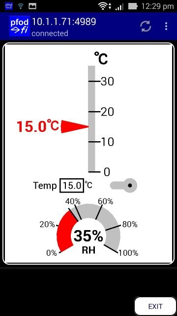
The sketch Test_a.zip has the component classes and a test sketch that positions and scales them on the screen. The instances of the GUI components are declared at the top of the sketch.
OnOffSlider _onoffslider(&parser, &dwgs); // create onOffSlider object and add to parser processing
RH_Gauge _rh_gauge(&parser, &dwgs); // create RH_Gauge object and add to parser processing
Setpoint _setpoint(&parser, &dwgs); // create Setpoint object and add to parser processing
T_Gauge _t_gauge(&parser, &dwgs); // create T_Gauge object and add to parser processing
Then in bool sendMainDwg() they are positioned and scaled before inserting into the main drawing. Here the main drawing is longer at 50 x 65.
bool sendMainDwg() {
  // main dwg just inserts desgined dwg
  dwgs.start(50, 65, dwgs.WHITE, false); //false means NO more to come
  parser.sendRefreshAndVersion(0);

  dwgs.pushZero(25.00,38.00,0.9); // position and set the scale for T_Gauge
  dwgs.insertDwg().loadCmd(_t_gauge).send(); // insert the temp gauge in the main dwg dwg
  dwgs.popZero();

  dwgs.pushZero(20.00,42,1); // position and set the scale for the setpoint
  dwgs.insertDwg().loadCmd(_setpoint).send(); // insert the setpoint component in the main dwg dwg
  dwgs.popZero();

  dwgs.pushZero(35.00,42.00,0.4); // position and set the scale for the OnOffSlider
  dwgs.insertDwg().loadCmd(_onoffslider).send(); // insert the onoffslider in the main dwg dwg
  dwgs.popZero();

  dwgs.pushZero(25.00,57.00,0.85); // position and set the scale for the RH gauge
  dwgs.insertDwg().loadCmd(_rh_gauge).send(); // insert the rh gauge in the main dwg dwg
  dwgs.popZero();

  dwgs.end();
  return true;
}
Finally in the loop() code the various GUI components are linked together
void loop() {
  _t_gauge.setT(_setpoint.getSP());

  if (_onoffslider.isOn()) {
    if (!timer.isRunning()) {
      timer.start(3000); // start if not already running
    }
  } else {
    timer.stop();
  }
  if (timer.justFinished()) {
    timer.restart();
    rh += 5;
    if (rh>100) { rh = 0; }
    _rh_gauge.setRH(rh);
  }

  handle_pfodServerConnection();
}
Here the temperature gauge reading is set by the setpoint input and
on/off slider controls starts/stops the update of the RH gauge with
some dummy data.
The main menu is set to refresh every 2sec to
update the temperature gauge and RH gauge with their new values. See
static unsigned long dwgRefresh = 2000; at the top if the
Test.ino sketch
The setpoint and on/off slider are updated immediately by their classed update methods. The setpoint and on/off slider command processing could be modified to update the main menu directly by calling sendMainMenuUpdate() directly instead of their own sendUpdate() methods.
This tutorial covered the free pfodGUIdesigner Android app for GUI designer and code generation. The general purpose pfodApp on an Android moble was used as the display interface. The designer lets you create your own GUI components with a drawing program and basic drawing elements and touchZones and touchActions. The generated code for each designed component gives a separate class for that component that can then be combined, positioned and scaled, to give the final Graphical User Interface to control your Arduino project from an Android mobile with pfodApp.
The touchZones provide 'hot' areas on the screen that send commands when the user touches them. The touchActions provide immediate feed back to the user that 'hot' area has been triggered. touchActionInputs provide a text input dialog box with configurable prompt and default text.
The final GUI design is very compact and needs less then 1K of memory and a few hundred bytes of ram to run and so can be run on wide variety of Arduino boards from Uno (with a communication shield) up. The communication between your Arduino board and pfodApp can be via either WiFi or Bluetooth or BLE or SMS. The free pfodDesignerV3 app for Android generates the basic connection sketch for may other boards and communication shields.
pfod has been under continual development for over a decade (pre-Android). The current version of pfodApp runs on Android mobiles from V4.4 onwards, so you can repurpose your old mobile as an Arduino user interface. pfodApp can connect to your Arduino device via WiFi, Bluetooth, BLE or SMS. The free pfodDesignerV3 Android app generates connection code for a large number of Arduino boards. So you can use the pfodDesignerV3 app to generate the basic connection sketch for your board when deploying your final GUI
The pfodApp operates like a micro browser. It takes its instructions from your Arduino sketch, via compact text messages and displays a hierarchical menu of buttons, sliders and drawings, as well as chart, text and numeric input screens, as requested by the messages sent by the sketch. The most flexible of these items is the drawing menu item. This pfodGUIdesigner designs a drawing menu item that displays your GUI and sends back commands to your Arduino as the user touches parts of the dwg.
AndroidTM is a trademark of Google Inc. For use of the Arduino name see http://arduino.cc/en/Main/FAQ
The General Purpose Android/Arduino Control App.
pfodDevice™ and pfodApp™ are trade marks of Forward Computing and Control Pty. Ltd.

Contact Forward Computing and Control by
©Copyright 1996-2020 Forward Computing and Control Pty. Ltd.
ACN 003 669 994


