
|
Home
| pfodApps/pfodDevices
| WebStringTemplates
| Java/J2EE
| Unix
| Torches
| Superannuation
|
| About
Us
|
|
|
Bluetooth Controlled Led Driver
|
by Matthew Ford 10th May 2009 (revised 23rd
February 2010)
© Forward Computing and Control Pty. Ltd. NSW
Australia
All rights reserved.
NO SMD required
An Android Controlled LED Driver is also described here – No Android programming required.
This is Part 2 of the tutorial. This part covers converting the Three Level Led Driver code to an interrupt driven program, integrating the RS232 module, controlling the led levels from your computer via RS232, and adding the Bluetooth hardware module. Finally some extensions will be suggested.
How to Code uC Interrupt Driven Programs
How to Avoid Interrupt Data Corruption
1) How to prevent interrupt routines from un-intentionally changing the values
2) How the main program can safely access Registers and SRAM updated by an Interrupt routine
The Basic uC Led Driver that this tutorial is based on used a very reliable and easy to program method of handling the Analogue to Digital Converter (ADC) interrupt. It used method 2) d) “Do all the processing inside the interrupt routine itself.” However while this is OK if there is just one interrupt, when you have to handle more then one interrupt it breaks Guideline 1 “Keep the Interrupt Code Small” Executing large blocks of code in the interrupt routine delays the handling of other interrupts. As we have seen in part 1, sending and receiving RS232 signals is time critical. So before we integrate the RS232 module into the Led Driver, we must first modify the Led Driver to be an interrupt driven program where the interrupts are handled quickly.
The original Led Driver code is in
ThreeLevelDriver.asm
, the
revised code is in 3LevelDriver.asm.
Most of the the code is the same. The main difference is that
i)
the Led Control code and the Process State Triggers code is now
called from the main loop,
ii) the ADC interrupt routine has
disappeared and
iii) there is a timer interrupt routine.
First lets look at how the ADC measurements are collected. Instead of using an interrupt we just “pole” the ADSC flag to see if the ADC has finished converting the next sample.
LED_CONTROL:
   sbic ADCSRA, ADSC
   rjmp RET_LED_CONTROL // ADSC still set no reading yet
If it has not finished then, the LED_CONTROL routine just returns, otherwise it reads in the ADC sample, starts another conversion and drives the led control output in the same way as the original code did. Since the next conversion is not started until the last sample has been read, there is no possibility of losing a sample or having it partially over-written by a new value while we are still processing it.
Next look at the timer interrupt. This is similar to the RS232 timer interrupt but using a different timer. Timer1 is set up to fire an interrupt every 2mS. The interrupt routine is very short and simple
TIMER1_COMPARE_A_INT:
    SAVE_SREG   // not used here but leave as standard interrupt preamble
    sbr TRIGGER_Flags, (1<<TRIGGER_Timer1)  // modifies SREG
    RESTORE_SREG
reti
It just sets a flag and returns. A routine in the main program, TIMER1_2mS, checks this flag and calls SWITCH_DEBOUNCE each time it is set.
TIMER1_2mS:
   sbrs TRIGGER_Flags, TRIGGER_Timer1
   rjmp END_TIMER1_2mS
   // else changed clear trigger now
   cbr Trigger_Flags, (1<<TRIGGER_Timer1)
   rcall SWITCH_DEBOUNCE
END_TIMER1_2mS:
ret
You can see a pattern developing in this program and the RS232 program. The interrupt routines do the minimum work possible, save results and then set flags to alert the main program that data is available or has been sent or that some action has happened.
The main program loop is
MAIN_LOOP:
    rcall LED_CONTROL
    rcall TIMER1_2mS
    rcall PROCESS_STATE_TRIGGERS
    rjmp MAIN_LOOP
The interrupts set the flags and save results and these three routines called from the MAIN_LOOP look for changes in the flag settings and use the results to control the led and process the push button presses.
The rest of the code of 3LevelDriver.asm is very similar to the previous ThreeLevelDriver code, pushing the button changes the state and loads a new led current set point. Note that because the led control and the loading of the new led current set point are called from the main program loop and not from the interrupt routine, there is no possibility of set point being changed half way through the led control routine, LED_CONTROL
To program the uC, start a new project, 3LevelDriver, as described in the previous tutorial Basic uC 3 Level Led Driver , and downloaded the 3LevelDriver.asm and copy it into the empty .asm file created by the project. Compile the code and program the uC. Remember to change the Input hex file to the 3LevelDriver.hex file on the Program tab of the AVR Dragon programming dialog.
You led driver should run as it did in the previous tutorial, with the button click cycling through the 3 levels of led brightness and then off.
The last bit of software programming that needs to be done it to merge the RS232 module with the 3LevelDriver. The merged code is in BluetoothLedDriver.asm.
Revision Notes: 23rd February 2010. Revised BluetoothLedDriver.asm to correct pin test at top of PIN_CHANGE_INT and limited maximum setpoint for the current to 1000. The ADC maximum reading is 1023 and you should always be able to measure more then you are trying to control to. For proportional control, 10% extra is typical, for on-off control (bang-bang control), used here, 2% is sufficient. See Basic uC 3 Level Led Driver for a description of how the on-off pulses are filtered to give a 'smooth' led control.
In this code the three methods of the main loop of the 3LevelDriver above have been moved to their own method, LED_CONTROL_PROCESSING and two new method have been added to the main loop, PROCESS_RS232 and SEND_ADC_READING.
The PROCESS_RS232 method processes the incoming characters from the RS232 module. '0' turns the led off, '1' sets low level, '2' sets medium level and '3' sets high level. Also 'u' and 'U' will increase the led setpoint while 'd' and 'D' will decrease it.
The SEND_ADC_READING method handles sending the ADC current reading back to the PC via the RS232 connection.
PROCESS_RS232 first checks if the RS232 module had just finished transmitting (the ADC reading) and if so sets it to receive characters. Otherwise the code checks if there is a new data byte has been received to be processed. Note the can occur even if the RS232 module is currently transmitting as the last byte received is not overwritten by a transmit. If there is a byte available, the code first saves it in Temp2 and then clears the RS232_STATUS_DATA_RECEIVED flag. The code to clear the flag is wrapped in disable interrupts block to ensure some other code does not try to update the RS232_STATUS at the same time. PROCESS_RECEIVED_CHAR is then called to process the character received and update the led setpoint accordingly.
SEND_ADC_READING is called every loop of the main loop, but just returns if the TRIGGER_2Hz is not set. The TRIGGER_2Hz is set every 0.5sec as part of the TIMER1_2mS code which is called by LED_CONTROL_PROCESSING code to update the push button debounce. If the TRIGGER_2Hz is set then we want to send the latest ADC reading, but first it checks if the RS232 is already occupied transmitting. If it is then the code just returns but leaves the TRIGGER_2Hz set so it will check again next loop to see if it can send. If the RS232 module is busy receiving a character then this code will interrupt the reception and transmit the ADC reading. Transmission takes precedence over reception so a burst of characters from the PC cannot prevent the transmission of the ADC reading each 0.5sec. Once the code had decided to send the ADC reading, it set the HEX values in the send buffer and calls RS232_TRANSMIT to send them. This code depends on RS232_TRANSMIT only being called from the main loop so that it is safe to update the transmit buffer globals once you have checked that the RS232 module is not transmitting.
To program the uC, start a new project, BluetoothLedDriver, as described in the previous tutorial Basic uC 3 Level Led Driver , and downloaded the BluetoothLedDriver.asm and copy it into the empty .asm file created by the project. Compile the code and program the uC. Remember to change the Input hex file to the BluetoothLedDriver.hex file and the EEPROM eep file to BluetoothLedDriver.eep on the Program tab of the AVR Dragon programming dialog.
To control the Led Driver from your computer, plug in the serial cable and set up the RS232 terminal connection as described in Communicating with your uC . When the terminal window opens it should immedately start displaying rows of the ADC 0x00 0x00 (assuming the led is off).
Click in the Terminal Window so that the key presses are sent to that program. If the terminal window is not the active window, the led will not be controlled by the keyboard.
You can also enable local echo for the terminal window by clicking “local echo” in the Setup → Terminal dialog box, so you can see you key presses in the window.
Press the '1' key, the Led should come on at Low and the ADC reading will change to about ADC 0x00 0x70. The reading will vary as the led current varies. Try the '2', '3' and '0' keys to change levels and turn the led off. The from the off press and hold the 'u' key. The led will increase to maximum intensity, about 0x03 0x15 = 787
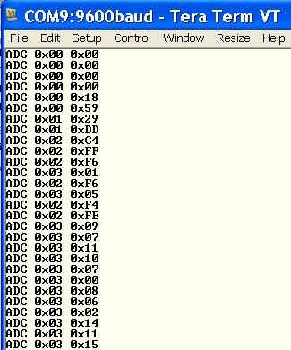
Note that this maximum Led current is less then the maximum setpoint of 1000. This is because of the 3.3ohm protection resistor in series with the Led and because I am using a 4.5V power supply. Now that you are satisfied that every thing is running correctly, you can short out the 3.3ohm resistor (I used a clip lead). With the 3.3ohm resistor out of the circuit, the led can be driven at maximum current. That is about 0x03 0xE8 = 1000 with '3' and a little higher with 'u' (about 1023). 1023 is the maximum reading of the ADC.
Now the software is all working, you can swap the RS232 cable connection for a Bluetooth connection. The circuit is shown below
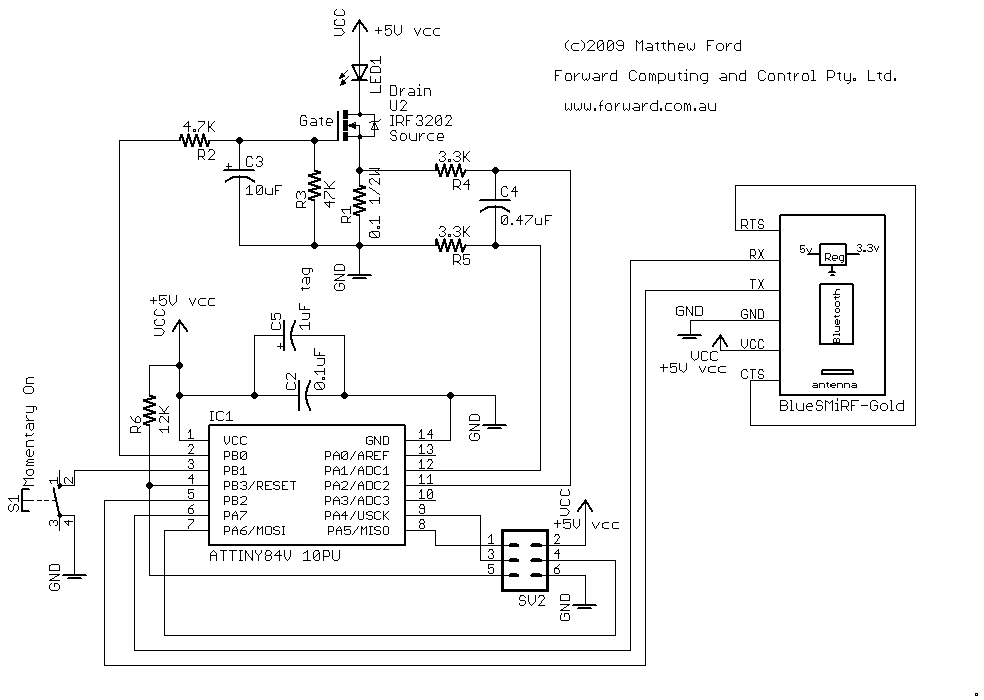
This
circuit does not show the 3.3ohm protection resistor that you can see
in the following photo.
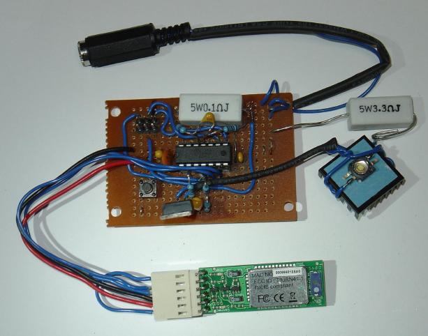
As you can see from the photo the 3.3ohm protection resistor is in series with the LED and is there to stop the LED burning out in the event the FET (U2) is turned on hard. Once you are sure every thing works as expected and you are not going to make any more changes, you can remove the resistor to get the maximum brightness from the LED (i.e. 500mA). The
RS232 Circuit Description section shows the 3.3ohm in its circuit.
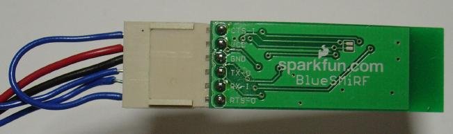
Comparing these two circuit diagrams, you can see that the BlueSMiRF-Gold bluetooth module replaces the MAX232, its associated capacitors and the 9 pin Serial D connector. The RTS and CTS connection (Request-To-Send to Clear-To-Send) that was previously done on the 9 pin D connector is now done on the plug the connects to the bluetooth module. As an alternative, there are a couple of small pads on the bottom of the bluetooth board, (visible below) that when connected together, will also connect RST to CTS. The bluetooth module's pin names are screen printed on the bottom of the module's pcb.
This module, supplied by www.sparkfun.com, has an on-board regulator and input and output level shifters so that you can drive the 3.3V bluetooth chip directly from the Attiny84's 5V supply and i/o pins. The regulator is a low drop out one so any supply voltage above about 3.5V should work.
The BlueSMiRF-Gold is uses the Roving Networks RN-41 sub-board complete with antenna. As supplied in the BlueSMiRF-Gold module, the RN-41 is set to 115,200 baud, 8 bits, No Parity, 1 stop bit, so you will need to configure the module to work at 9600. The Advanced User manual, rn-bluetooth-um.pdf , is available www.rovingnetworks.com. The User Guide, RN_BlueportII-ref-guide.pdf, can be down loaded from both www.sparkfun.com and www.rovingnetworks.com. Both these documents are basically the same and detail three ways of configuring the RN-41, via switch settings, via its RS232 connection or directly via the bluetooth connection. The BlueSMiRF-Gold board does not provide access to the switch contacts on the RN-41 module so you have to use one of the other two configuration modes. Which one you use depends on whether or not your computer has bluetooth built in. My computer has bluetooth build in, so I will cover configuring the module via bluetooth first.
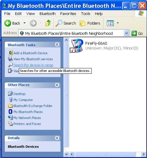
To configure the BlueSMiRF-Gold via the bluetooth connection, power up your Bluetooth Controlled Led Driver and then check Bluetooth control panel on your computer after first making sure your computer's bluetooth system is enabled. The following pictures are from Window XP. Open “My Bluetooth Places” from the Programs list and if the FireFly device does not show up automatically try “searching for devices in range”
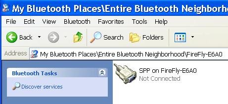
When you find the device double click on it to discover its services. Double click on the SPP service to connect.
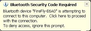
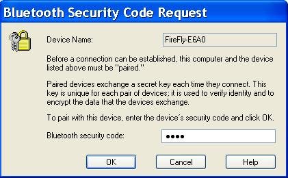
It may then pop up a dialog box asking for authentication. If it does type 1234 in for the password.
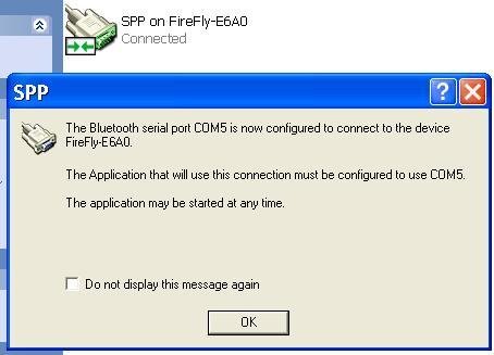
When it connects you will get a dialog box telling you which COM port the FireFly Bluetooth Module is connected to.
The green led on the module will light when connection is made.
You can now start Tera Term and select Serial COM5. Unlike the RS232 connection, you will not see the display of the ADC current reading, because the default BlueSMiRF-Gold baud rate setting 115200 so the RS232 software in the Led Driver uC is not communicating correctly with the bluetooth module.
Note: The baud rate setting on Tera Term has absolutely no effect on the remote FireFly bluetooth module.
To change the setting of the Led Driver bluetooth module, you need to get into CMD mode by typing $$$. This must be done within 60sec of powering up the module, so once you have authorized the bluetooth connect, as described above, power down the Led driver and power it up again and connect via bluetooth, open the Tera Term window, set local echo (via the setup - > Terminal dialog box) and type $$$ with in 60secs of powering up. The red led on the bluetooth module will flash rapidly.
You can now configure the remote module for 9600 baud by typing the command SU, 9600 and press Enter. The module will respond AOK at the front of the same line. Then power down the led driver and power it up again and the next time you connect and start up Tera Term you will see the ADC current readings as before and be able to control the led brightness using the 'u' and 'd' and '1' '2' '3' '0' keys. Remember to click in the Tera Term window first so that your keystrokes are sent to the Led Driver.
If your computer does not have bluetooth built-in, then you need an other UBS Bluetooth module to connect to the led driver bluetooth module. But first you have to set the baud rate of the led driver module to 9600. To do this use the RS232 chip and Serial D connector you previously had connected to the led driver and leaving the power connected to the led driver board for both the RS232 driver chip and the bluetooth module, connect the BlueSMiRF-Gold Tx to Pin 10 of the MAX232 and connect Rx to pin 9 of MAX232. Now when to power up, you can connect to the bluetooth module via your serial port (at 115200 baud). The following the instructions above, within 60 secs of powering up type $$$ and then issue the command SU,9600 to set 9600 baud. The change in baud rate will not actually take place until you turn the power off and on again. Once you have set the baud rate, you can remove the MAX232 pcb and re-connect the BlueSMiRF-Gold Tx and Rx to the uC pins as shown on the schematic above.
Now plug in the Bluetooth Modem - BlueDongle USB (from SparkFun.com) and when you open Tera Term you will see a new USB com port.

The default baud for this USB Bluetooth module is also 115200, so you need to change the Tera Term baud to match using the Setup - > Serial Port dialog. Also set local echo again from the Setup - > Terminal dialog
Then type $$$ (within 60sec of powering up the USB bluetooth module) to get into CMD mode. Then type I,10 to look for other bluetooth devices. After a little while the address of the Led Drive bluetooth module should be displayed (make sure it is powered up also). For example 00066601E6A0,FireFly-E6A0,1F00 Then carefully type SR,00066601E6A0 , replacing the 00066601E6A0 with the address of your own Led Driver bluetooth module, so that the USB and Led Driver modules will be linked. Finally type C to tell the USB bluetooth module to connect to the Led Driver module and you should see the ADC current readings being displayed.
Unfortunately once you power down either module you need to get the USB module back into CMD mode and type C to connect again. You can make connection automatic by setting the USB module to be a Auto-connect Master mode. For convenience we will set the USB baud rate to 9600 also as that is what Tera Term comes up as.
To do this, power down and up the USB bluetooth module (unplug and plug in again). Close and open Tera Term and select the USB com port and set 115200 baud rate and local echo. The type $$$ to get into CMD mode. Type SU,9600 to set 9600 baud (next time the USB module powers up) and also type SM,3 to set the USB module to Auto-connect Master mode. You can check your settings by typing D- which will display the USB bluetooth module settings. Then unplug the USB module, close Tera Term and plug the module back in. When the USB bluetooth module is plugged back in you will notice that the Led Drive bluetooth module led goes green, i.e. connected. Then on opening Tera Term and selecting the USB Com port you will see the ADC readings and (after clicking in the Tera Term window) you will be able to control the Led Driver via your keyboard.
Here are a few suggestions for extending this project.
Debugging live code
A Remote control
User changeable modes and settings
This will be my initial use for this project. I am building a NiMh battery charger into my latest torch. The battery charger has a number of states, initial charge, fast charge, over voltage, over temperature, topup charge, etc. It also has a delta T termination condition which requires the temperature to be measured every 30 secs to check the rate of rise. By adding additional command characters to this project's code, I will be able to request the current mode of operation and get the latest temperature, delta T readings and charging current while the battery is charging.
Using essentially the same circuit, but without the Led and power fet, you can make a remote control for your bluetooth controlled led driver. The previous section showed how to connect two bluetooth modules to each other and the Attiny84 has ample spare inputs for dedicated buttons for ON, OFF, Up and Down.
From the remote control or via commands from Tera Term or via a dedicated program, you can allow the user to change the mode of operation of your led driver. Add a timed auto-turnoff feature with adjustable timeout. Add more levels. Set the levels, etc. Using single character commands via bluetooth is much more convenient for the user, then going through a complicated series of button presses to change the mode of operation of the led driver.

Contact Forward Computing and Control by
©Copyright 1996-2020 Forward Computing and Control Pty. Ltd.
ACN 003 669 994