
|
Home
| pfodApps/pfodDevices
| WebStringTemplates
| Java/J2EE
| Unix
| Torches
| Superannuation
|
| About
Us
|
|
|
ESP8266-01 Wifi Shield
|
by Matthew Ford 23rd October 2015
(originally posted 29th June 2015)
© Forward
Computing and Control Pty. Ltd. NSW Australia
All rights reserved.

This ESP8266-01 WiFi Shield is an alternative to the Cheap/Simple Wifi Shield for Arduino and other micros. The Cheap/Simple Wifi Shield for Arduino and other micros uses an Adafruit HUZZAH ESP8266 module and is the simplest to wire up. However if you already have an ESP8266-01 module, you can use these instructions to make a WiFi Shield using it.
If you have one of the other ESP8266 bare modules, provided the module has GPIO0 and GPIO2 available, then you can use these instructions. If the module makes GPIO15 accessible YOU MUST connect it to GND via a resistor with a value between 3K3 and 10K.
The first iteration of this project was an ESP8266 WiFi Addon for Arduino using pfodWifiConfigV1. The instructions here largely supersede that page.
Uses the inexpensive and readily available ESP8266-01 module :- Other ESP8266 modules can also be used
Simple to use :- The 5V and 3.3V compatible shield acts as UART to WiFi bridge. It sets up a server on the IP and port you configure and once connected just passes data to and from the Serial connection. No libraries are need in the connecting micro, just a Serial (UART) connection, so it can be used for any micro-processor that has a serial port. It can also be modified to be configured to make a client connection (with optional login) to a remote server.
Simple to configure :- Shorting out a link and powering up the shield, puts it into configuration mode. In this mode it creates a secure Access Point that you can connect to via your mobile or computer. Then opening http://10.1.1.1 presents a web page where you can configure your network's name and password and the IP and port number the shield should listen on for connections. The configuration web page uses HTML5 validation to check the user's settings.
This ESP8266-01 WiFi Shield needs the following parts, or similar. The prices shown here are as at 30 June 2015 and exclude shipping costs:-
WiFi
Module - ESP8266-01 – US$6.95
Uno
Protoshield – US$1.88 (or ProtoShield
Basic for Arduino from Jaycar AU$4.95)
Digikey
36-pin header – US$1.44 (or 4 off Solderless
Headers - 10-pin Straight from SparkFun US$1.50 or 40
Pin Header Terminal Strip from Jaycar AU$0.95)
4 off 3K3
resistors – Digikey – US$0.52 (or 3K3ohm
1/2 Watt 1% Metal Film Resistors – Pk.8 from Jaycar
AU$0.55) (These pull-up resistors can
be any value in the range 3K3 to 10K)
1
off 330R resistor – Resistor
330 Ohm 1/6 Watt PTH - 20 pack US$0.95 (or 330ohm
1/2 Watt 1% Metal Film Resistors – Pk.8 from Jaycar
AU$0.55)
2 off 1N5819 Schottky Diode – Digikey
US$0.78 (or Jaycar
AU$1.60) (Any Schottky Diode will
do)
DFROBOT
Breadboard Power Supply 5V/3.3V – US$4.55 (or a 5V to 3V3
regulator and two capacitors (0.1uF
and 10uF)
e.g. LD1117V33,
see the datasheet
for circuits details, ~US$2.65 for the capacitors and regulator)
Total Cost ~$17.00 + shipping (as of June 2015)
To program the shield with the push button configuration and UART to WiFi bridge program, you also need a USB to Serial cable. Here a SparkFun's USB to TTL Serial Cable (US$9.95) is used because it has nicely labelled ends and has driver support for wide range of OS's, but you can also use Adafruit's USB to TTL Serial Cable - Debug / Console Cable for Raspberry Pi which is the same price.
Including the programming cable, the cost for just one WiFi Shield is ~US$26.95. A quick search finds Arduino WiFi Shields costing a minimum of US$30 up to over US$70. So even including the once off cost of the programming cable this shield is cheaper than the other available shields, as well as being much easier to configure and use.

(click
image to download pdf
of the schematic)
The above schematic shows the arrangement of the parts needed for this shield. Most of the resistors are just pull-ups for the ESP8266-01 module. The 1N5819 diodes protect the ESP8266-01 inputs from the micro-processor's 5V outputs. The 330ohm (R6) resistor provides protection against shorting out the ESP8266-01 TX output, if the micro-processor's D1 is accidentally made an output.
Some sort of 3V3 supply is needed. The Arduino UNO's 3V3 pin is not strong enough to supply the ESP2866 module. Here a DFROBOT Breadboard Power Supply 5V/3.3V daughter board has been used, but you can also use a discrete 3V3 voltage regulator, like LD1117V33, and two capacitors.
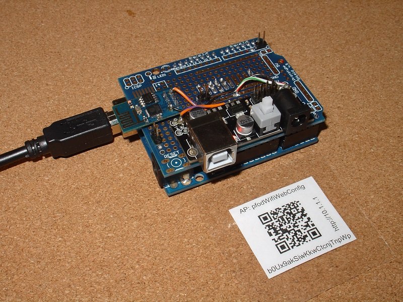
Here are the top and bottom views of the completed board.


Make sure you carefully check the wiring when you are finished, particularly the wiring to the pins of the ESP8266-01. It is easy to wire to the wrong pin when you turn over the board to wire from the bottom.
The WiFi Shield needs to be programmed once, only, and never again, with the web page configuration and the Serial to WiFi Bridge code.
To program the shield follow the instructions given on https://github.com/esp8266/Arduino under Installing With Boards Manager. When opening the Boards Manager from the Tools → Board menu and select Type Contributed and install the esp8266 platform. This project was compiled using the ESP8266 version 1.6.4-673-g8cd3697. Later versions well be better but may have their own bugs as the platform is evolving rapidly.
Close and re-open the Arduino IDE and you can now select “Generic ESP8266 Module” from Tools → Board menu.
You also need to install the latest version of pfodWifiConfig.zip which handles the storing and retrieval of the settings in EEPROM
a)
Download this pfodWifiConfig.zip
file to your computer, move it to your desktop or some other folder
you can easily find
b) Then use Arduino 1.6.5 IDE menu option
Sketch
→
Import
Library →
Add
Library to
install it.
(If Arduino does not let you install it because the
library already exists then find and delete the older pfodWifiConfig
folder
and then import this one)
c) Stop and restart the Arduino IDE and
under File->Examples you should now see pfodWifiConfig.
After you have installed the pfodWifiConfig library, open the Arduino IDE and copy this sketch, ESP8266_01_WifiShield.ino, into the IDE. Before you program the shield, you need to set your own password for the configuration access point.
In configuration mode, the WiFi Shield sets up a secure Access Point called pfodWifiWebConfig with a password contained in a QR code attached to the shield. This secure connection prevents anyone listening in on your connection while you are setting your real network's ssid and password. You should generate your own password for your shields. A SecretKeyGenerator java program is available here which generates random 128bit keys and writes out QR.png files. Another alternative is to use QR Droid Private (from Google Play) to create a QR Code for your own chosen password.
In either case you need to update the #define near the top of the sketch with your own password.
// =============== start of pfodWifiWebConfig settings ==============
// update this define with the password from your QR code
//  http://www.forward.com.au/pfod/secureChallengeResponse/keyGenerator/index.html
#define pfodWifiWebConfigPASSWORD "b0Ux9akSiwKkwCtcnjTnpWp"
You can also set your own configuration Access Point name, if you wish.
To program the shield, remove it from the Arduino board, short out the FLASH_LINK (shown here with a blue shorting link in the middle of the board) and connect the USB to Serial cable as shown in the photo. Check the photo and your wiring.
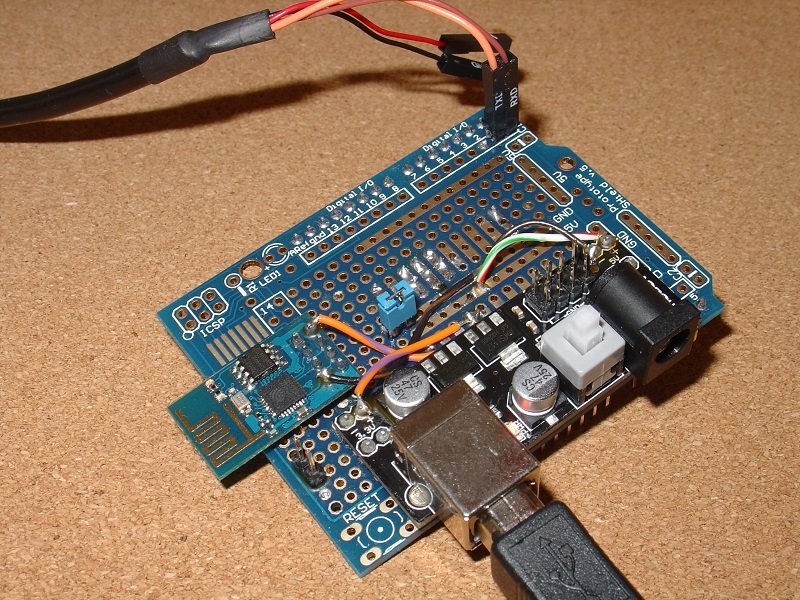
The
RX lead connects to D0 and the TX lead connects to D1.
To put the ESP8266-01 into programming mode, plug in the USB cable (bottom right) that supplies power to the shield. If the power light does not come on, press the white push button on the power supply daughter board.
This photo is for the SparkFun USB to Serial cable. If you are using the Adafruit cable, it does not have the terminals marked but green is TX and white is RX.
Plug in the USB to Serial cable into your computer and select it COM port in the Tools → Port menu. Leave the CPU Frequency, Flash Size and Upload Speed at their default settings.
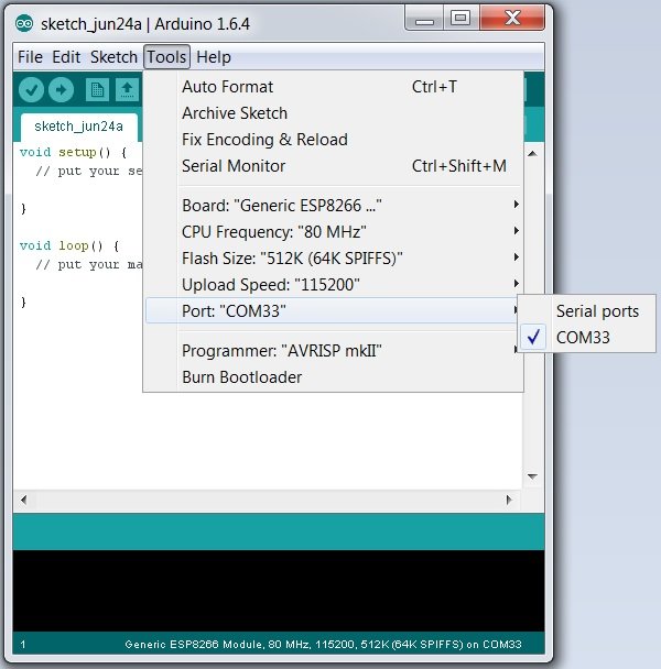
Then select File → Upload or use the Right Arrow button to compile and upload the program. Two files are uploaded. If you get an error message uploading check your cable connections are plugged in the correct pins and try again. Once the programming is completed, remove the shorting link from FLASH_LINK.
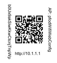
You will need your unique configuration access point password each time you need to configure the shield, so it is convenient to attach it as a QR code to the shield (or its case). Here is the Open Office presentation file that was used to print out the QR code and connection details for this project. Replace the QR code and password text with your own unique one to complete the shield.
Any WiFi shield needs to be configured with the network name and password of the local network. It also needs to be given an IP and port number to listen on for connections. All other WiFi shields have the IP and port no hard coded in the sketch and either hard code the network name and password or use a proprietary method with proprietary apps to connect to the local network. This is very restrictive when you have multiple devices in an evolving environment. This WiFi Shield uses an open source web page method to configure both the network name and password, and the IP address and port No.
The ESP8266-01 has a very limited number of available outputs, just GPIO0 and GPIO2. In this design, after powering up, the code in the ESP2866-01 checks if GPIO2 is grounded and if so sets the ESP8266-01 in config mode. However the grounding of the GPIO2 input must be delayed until after the ESP8266-01 has finished powering up. If GPIO2 is grounded during power-up the ESP8266-01 module does not start up normally. This delay in grounding GPIO2 is achieved by connecting the ground side of the CONFIG_LINK to Arduino's D2 pin which is initially a high impedance input. Then in the Arduino setup(), after a slight delay, D2 is made an output and driven LOW which will ground GPIO2 if the CONFIG_LINK is shorted out.
So to configure the shield you need to load a program into the Arduino which has the following statements at the top of its setup() method
void setup() {
  delay(1000); // wait here for a second let ESP8266 complete powering up
  // before making D2 LOW
  // this also skips the WiFi Shield's debug output on power up
  // before starting the Serial connection.
  pinMode(2,OUTPUT);
  digitalWrite(2,LOW); // enable grounding of GPIO2 only after ESP8266 starts up
  …...  other set up code here
Here is the minimal program required.
void setup() {
  // put your setup code here, to run once:
  delay(1000); // wait here for a second let ESP8266 complete powering up
  // before making D2 LOW
  // this also skips the WiFi Shield's debug output on power up
  // before starting the Serial connection.
  pinMode(2,OUTPUT);
  digitalWrite(2,LOW); // enable grounding of GPIO2 only after ESP8266 starts up
}

void loop() {
  // put your main code here, to run repeatedly:
}
So to test out the ESP8266-01 WiFi Shield config
mode, remove the WiFi Shield and select your Arduino board as the IDE
board and load
this program into your Arduino.
Then plug the ESP8266-01 WiFi
Shield back into the Arduino and short out the CONFIG_LINK (blue
shorting link in the bottom left of the picture) and apply power to
the Arduino.

In
this config mode the ESP8266 module sets up a secure access point
with the name pfodWifiWebConfig.
This access point will show up on your mobile and on your computer.
To connect to this access point you will need to enter the unique
password for your shield. You can type the password in by hand but it
is easier and more reliable to scan the QR code you previously
attached to your shield, using a QR scanner app, such as QR Droid
Private.
 Then copy and paste the password into your
mobile's WiFi setting screen to connect your mobile to the
configuration access point.
Then copy and paste the password into your
mobile's WiFi setting screen to connect your mobile to the
configuration access point.
Then open a web browser and type in the URL http://10.1.1.1 This will return the configuration web page.
The WiFi Shield automatically fills in the Network SSID with the local network with the best signal strength. Which will usually be the one you want. If not just overwrite that entry. You must enter a Network SSID and password and portNo. The IP address field is optional. If you leave it blank, the WiFi Shield will use DHCP to get its IP address on your local network. It is often easier to specify a specific IP address so you can easily connect to this shield.
If your browser is HTML5 compliant then the web page will validate the input before sending it.

When you click the Configure button, the WiFi Shield will process the results and store them in EEPROM and then display a page like.
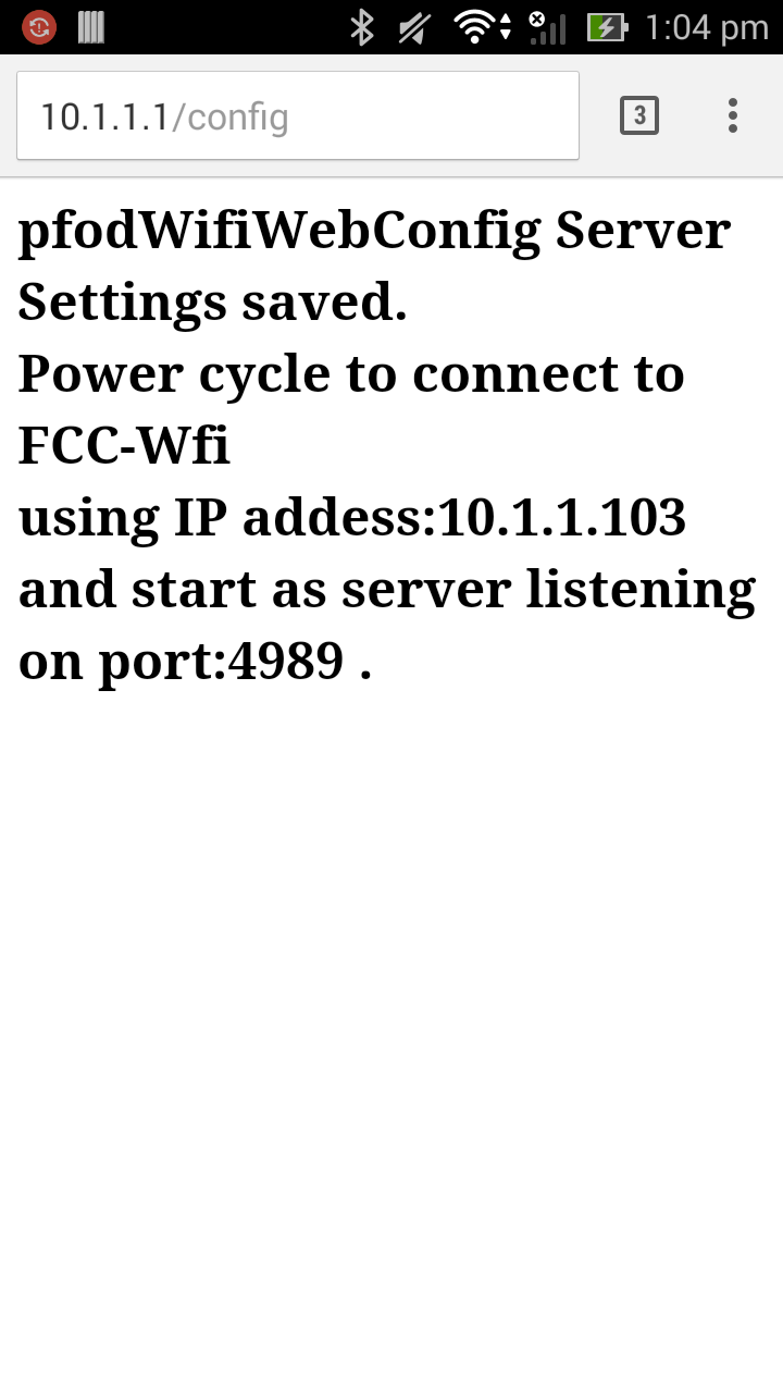
In a complete project, you would mount a momentary push button on the outside of your project's box connected to the CONFIG_LINK, and instruct the user to press the push button and then power up the device to get into config mode. The code you loaded into the ESP8266-01 also drives the ESP8266's GPIO0 pin LOW when the module is in config mode, so you can connect a 270ohm resistor and LED between the 3.3V rail and GPIO0 and mount the LED on the outside of the box, to indicate to the user that they are in config mode.
As mentioned above any sketch you load into your Arduino, or other micro-processor, needs to, after a short delay, set D2 low in setup() in order to enable the CONFIG_LINK. Other than that, to receive and send data via WiFi, from your sketch, you just read and write to your serial port (connected to D0,D1) at 9600 baud.
The example here uses an Arduino UNO but you can use any micro-processor, either 5V or 3.3V based that has a UART. If you use a 3.3V micro-processor, you will need to supply 5V to the WiFi Shield's power supply. This 5V will also be connected to the shield's 5V pin, so you need to check that this is acceptable for the micro you are plugging the shield into.
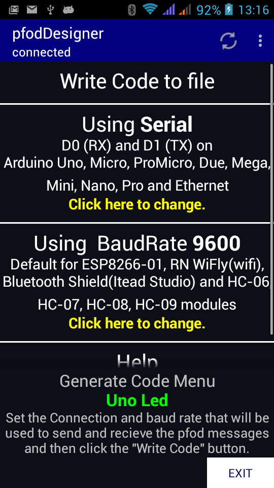
As a test of this shield, pfodApp was used to turn the Uno's LED on and off via WiFi. First the pfodDesigner was used to design a simple menu.

Then the code was generated for the Serial connection at 9600 baud and transferred the file to the PC, using wifi file transfer.
Then
the sketch's setup() method was modified to add the code to enable
the CONFIG_LINK
void setup() {
  delay(1000); // wait here for a second let ESP8266 complete powering up
  // before making D2 LOW
  // this also skips the WiFi Shield's debug output on power up
  // before starting the Serial connection.
  pinMode(2,OUTPUT);
  digitalWrite(2,LOW); // enable grounding of GPIO2 only after ESP8266 starts up
The complete sketch, ESP8266_UnoLedControl.ino is here. Note there is no special WiFi code, the sketch just reads and writes to the Serial output.
Remove the WiFi Shield, select Tools → Board →
Uno in the Arduino IDE and program this sketch into the UNO.
NOTE:
you must remove the WiFi shield to program the UNO because the USB is
connected to the UNO's TX/RX pins.
Plug the WiFi Shield back in, it will automatically connect to your local network and start a server on the port you configured. In pfodApp you can set up a connection for this device. See pfodAppForAndroidGettingStarted.pdf for the details
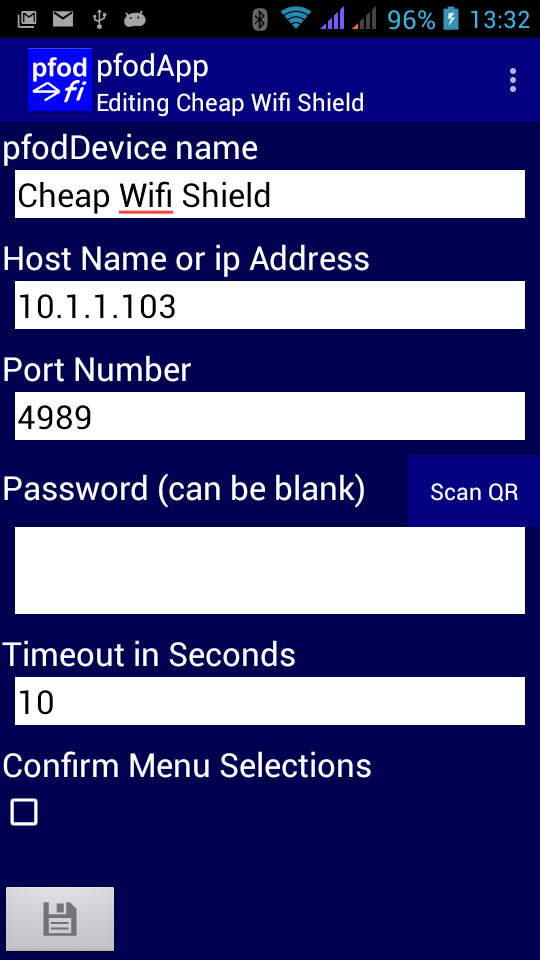
Then connect to turn the Uno's LED on and off from your Android mobile via wifi.
That's it finished!!
As presented here the WiFi shield can be configured to run as a server listening on a specified IP and port No. However the pfodWifiConfig also provides support for storing and retrieving Client settings as well as Server settings. So by adding these fields to the configuration web page and saving/loading the Client values, you can also use this WiFi Shield to connect to a remote server, with a client username and password, and upload data to there.
As mentioned above, in a real application you would mount a momentary push button on the outside of your project's box connected to the CONFIG_LINK, and instruct the user to press the push button and then power up the device to get into config mode. The code you loaded into the ESP8266-01 drives the GPIO0 pin LOW when the module is in config mode, so you can connect a 270ohm resistor and LED between the 3.3V rail and GPIO0 and mount the led on the outside of the box, to indicate to the user that they are in config mode.
pfod provides the option of 128bit security for Wifi and SMS connections. However that library uses about 6K bytes of program space and an additional 400 bytes of Ram. The Arduino UNO is very limited in both program space and RAM, so moving the 128bit security into the WiFi Shield would free up extra space for you sketches in the Arduino.
This ESP8266-01 WiFi Shield uses the cheap and readily available ESP8266-01 module. Other ESP8266 modules can also be used.
Once programmed you never need to program it again to set or change the network settings. They can all be set via a web page on a secure temporary WiFi network.
It is simple to interface to any micro that has a UART and works with on both 5V or 3.3V micro-processors.
No libraries are required to connect to this shield. It runs as a simple Serial to WiFi bridge.
AndroidTM is a trademark of Google Inc. For use of the Arduino name see http://arduino.cc/en/Main/FAQ
The General Purpose Android/Arduino Control App.
pfodDevice™ and pfodApp™ are trade marks of Forward Computing and Control Pty. Ltd.

Contact Forward Computing and Control by
©Copyright 1996-2020 Forward Computing and Control Pty. Ltd.
ACN 003 669 994