
|
Home
| pfodApps/pfodDevices
| WebStringTemplates
| Java/J2EE
| Unix
| Torches
| Superannuation
| CRPS Treatment
|
| About
Us
|
|
|
pfodWeb
|
by Matthew Ford 22nd October 2025 (originally posted 24th July
2025)
© Forward Computing and Control Pty. Ltd. NSW
Australia
All rights reserved.
This is the second tutorial on using
pfodWebDesigner to create interactive and responsive GUI for pfodApp
and the free, open source, pfodWeb.
This tutorial will cover
making copies of an existing control and inserting multiple controls
into a single, main, drawing, handling the commands sent and updating
the GUI with the current state.
Your micro serves all the
necessary code to run the web page controls. No third party js
libraries or internet access is needed.
pfodWeb
is a free web based partial
replacement for the paid Android app, pfodApp.
pfodWeb runs in a browser and connects to your Arduino board via
either Serial or BLE or HTTP. Using Serial you can connect to any
Arduino board and display the interactive controls it serves. pfodWeb
runs competely off-line. No internet connection is needed. Just
install the pfodParser library and open the index.html in the pfodWeb
sub-directory of the pfodParser library. The interactive controls are
completely defined by the code (generated by pfodWebDesigner) in your
Arduino. Very compact pfod
messages are used to send the controls and receive the user's
commands.
If your Arduino board supports HTTP and has a file
system of 200Kb, then you can load the all pfodWeb files onto your
microprocessor and serve them directly from there.
pfodWebDesigner is a free web based replacement for the free Android app, pfodGUIdesigner. pfodWebDesigner allows you to design interactive and responsive user interfaces for your microprocessor. pfodWebDesigner generates Arduino code that works with all pfodDevices that connect via Serial, Bluetooth, BLE, SMS and WiFi, not just those that have WiFi support. See how to install pfodWebDesigner and Using pfodWeb Designer to Create GUI's. Individual pfodWebDesigner controls are stored as JSON files which you can duplicate, modify and reuse in other designs. Each reused control can be individually scaled and positioned in the final design.
Introductory
Tutorial – Covers setting up the pfodWeb
Designer local server and install the pfodWeb support on an ESP32. A
simple press button example illustrates touchZone and
touchAction.
Reuse Controls with insertDwg –
This one. Covers copying dwgs and using insertDwg to insert multiple
copies into the main drawing.
touchActions
for Instant Feedback – Covers
using touchActions to give instant feedback in a slider
control.
TouchActionInput
for text/number entry – Covers
using touchActionInput to input text / numbers to your micro
Building
Reusable Controls – Covers building a re-usable popup help
button component.
pfodWeb is free and open source. If you want to support this work,
purchase the Android pfodApp
which will work with the same code developed here and which provides
more features such as charting and data logging.
See the free
pfodDesigner
Android app for creating menus and charts for pfodApp.
See the Introductory Tutorial for the parts list and the Installation instructions. Physical parts consist of just an Arduino board, e.g. Dfrobot ESP32 board or other Arduino board. (An UNO does not have enough memory to run these examples)
This tutorial builds on the previous one, but you can start here by loading this file, LedOnOff.json, into pfodWebDesigner.
Each drawing you insert into the main drawing has to be unique, so you need to make copies, with different names, if you want to insert multiple instances of essentially the same drawing, e.g. a button
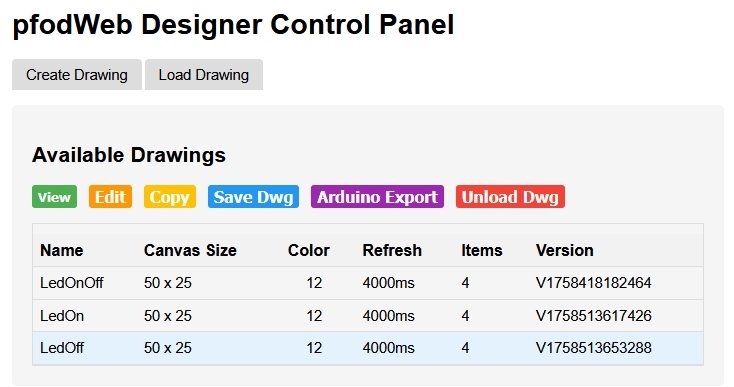
Having loaded the LedOnOff drawing into pfodWebDesigner, click
Copy to make a copy. Call it LedOn. Then Edit
LedOn and change the Label text to Turn Led On
Go
back to the control panel and make another copy called LedOff
and edit it to have a White
text, Turn Led Off,
on a Black rectangle.
Note that the labels still need to be indexed even though they will not be updated AND they need to be below the indexed rectangle in the list of each drawing's items. This is because indexed items are layered (drawn) in order of their numeric index which is assigned by pfodParser in the order the item is processed for sending to pfodApp / pfodWeb. Higher indices go on top.
The rectangle needs to be indexed so it has a reference for updating when 'touched'. If you un-index the label or move it above the rectangle, it will be completely covered and will not be visible.
Items without Use
Index checked are drawn first
in the order they are received. That is in the order they appear in
the list of item. Then indexed items are drawn in index order. That
is in the order they appear in the list.
The index name under Use
Index is the name of the code
variable that holds the numeric index. Changing that name has no
effect on the actual numeric index assigned.
It is
often helpful to change idx_1 etc to say idx_OnButtonText
Create a new drawing called TwoButtons. Size 40 x 15, Silver (light Grey, Color 7) background and 5sec refresh.
Open it in Edit
and Add New Item and
choose Insert Drawing.
From
the drop down list of loaded drawings choose LedOn
Note: The background color of the LedOn dwg is ignored. Only its drawing items are added. Any refresh interval set on an inserted drawing is also ignored. The refresh interval of the main drawing, TwoButtons, is used.
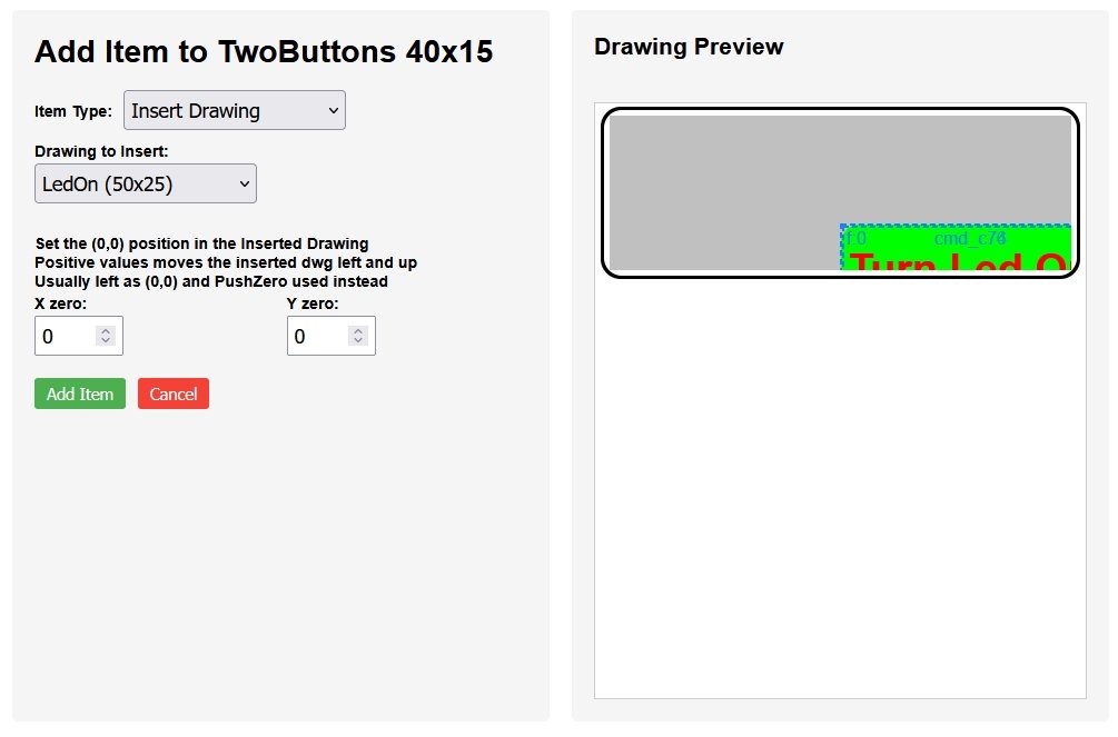
By default when you insert a drawing, each drawing item of the inserted drawing occupies its original position and size. So inserting a drawing with a rectangle 18 x 7 at position (25,12) in a drawing that is only 40 x 15, will clip the inserted rectangle.
When the main drawing is being processed for display, the drawing items of each inserted drawing are merged into the final list of drawing items. Un-indexed items of the inserted drawing are inserted in the position (order) the inserted drawing in found in the main drawing list of items. Un-indexed items that occur later overlay (cover) earlier ones.
The indexed items of the inserted drawing are added in their index order. pfodParser assigns unique numeric indices to each pfodAutoIdx indexed item it servers in the order it is served. For drawings with inserted drawings, the main drawing is completely served first and then the inserted drawings are requested by pfodWeb, in the order they occurred in the main drawing.
This means the auto generated numeric indices of all inserted drawing will be higher than, and can overlay, any indexed item in the main drawing and the indexed items of later inserted drawings will be higher, and can overlay, any indexed item of earlier inserted drawings.
You can adjust this by changing the order of the inserted drawings, or by manually setting your own numeric indices, instead of using the generated pfodAutoIdx variables, but that is usually not required or recommended
You can reposition the inserted
drawing by using its X and Y zero settings. These set the Column,Row
value of the inserted drawing that is positioned at (0,0) in the main
drawing.
Increasing the X,Y moves the inserted drawing to the left
and up. Negative and floating point numbers are accepted. Try
changing the values and see how the inserted drawing
re-positions.
Reset them to 0,0 and click Add Item.
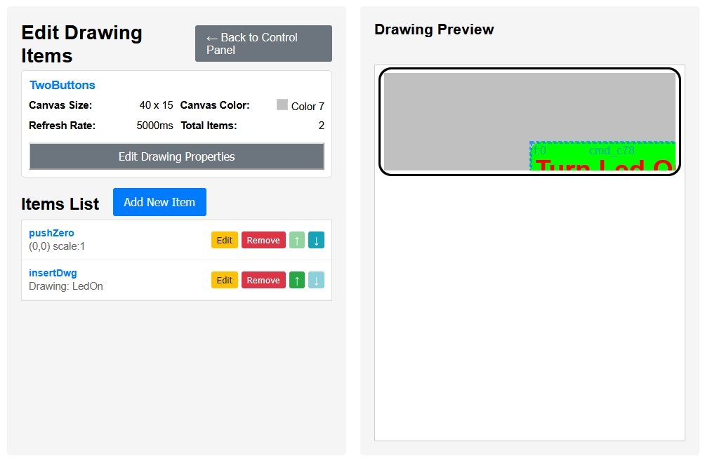
As you can see from above, the
inserted drawing is the wrong size and in the wrong position. The
pushZero command changes the position and scale for all
following drawing items, until a matching popZero is
found.
pushZero commands can be nested so you can use them
in the main and inserted drawings.
Click Add New Item again and add a pushZero item and click Add Item to accept it. Then in the Item List click the up arrow for the pushZero to move it above the insertDwg.
Then click on Edit in the pushZero row to edit it in its new position. Set the scale factor to 0.5 and adjust the X, Y to position the inserted LedOn drawing.
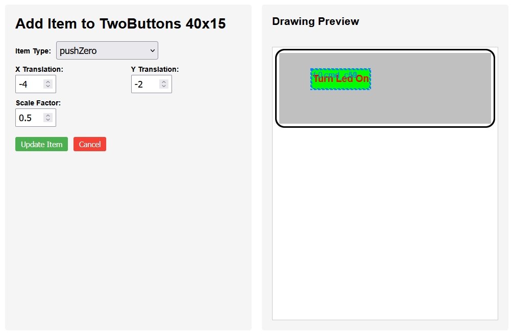
Click Update Item
to save the changes.
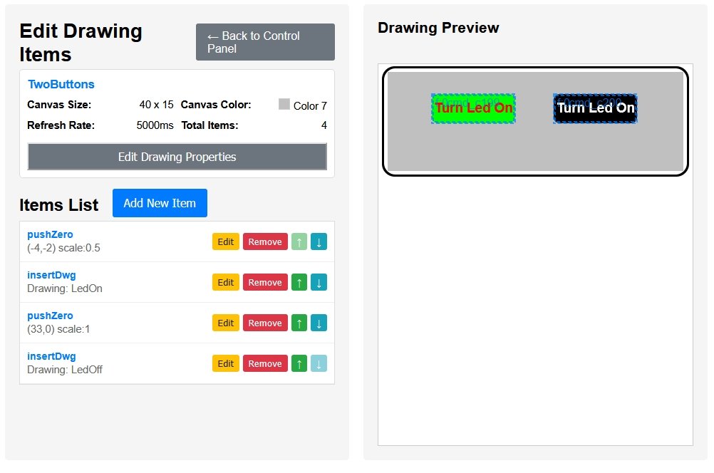
Insert the second LedOff drawing. You can either add a
popZero and another pushZero, or it is easier just add
another pushZero which will inherit the 0.5 scaling and Y
translation that currently in effect.
This will keep the LedOff
drawing with the same scale and Y position as the LedOn drawing.
Position the new pushZero above the LedOff inserted drawing and set its X translation to 33 to position the LedOff to the right of the LedOn dwg.
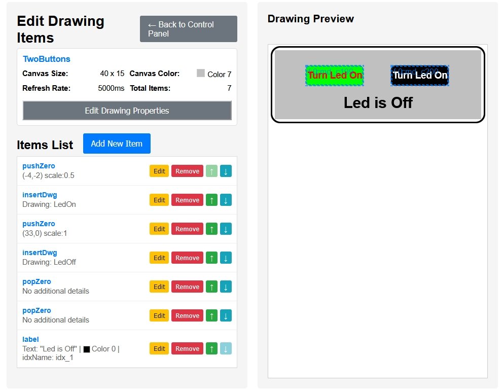
Add two popZeros to restore the original (0,0) position and scaling of 1.0 and add an indexed label to the main drawing to show the current state of the Led on or off. It is indexed because the label will be updated with the current led state.
Remember you can use floating point numbers for the X,Y positions to put the label just where you want it.
To back to the Control Panel. You can also view the final design
from there.
Then click the Arduino Export button to
generate the Arduino serial sketch, TwoButtons_serial.zip.
That
Arduino code zip file also includes the json files for the all the
drawings so you can reload them for later editing.
The sketch needs code to turn the board led on and off as the buttons are clicked and to update the “Led is Off” text to reflect the current led state. The final code is in TwoButtons_serial.zip
The LedControls.cpp / .h files are reused from the previous tutorial. The LedOnOff.h is included in Dwg_LedOnOff.cpp and in LedOnOff_serial.ino and initializeLedControls(); called at the end of setup();
In Dwg_TwoButtons.cpp file update the sendIndexedItems() to calls buttonText(), textColor() to get the text to display for the current state of the led. Here On is RED and Off is BLACK text.
#include "LedControls.h"
 . . .
void Dwg_TwoButtons::sendIndexedItems() {
  dwgsPtr->label().idx(idx_1).color(textColor()).text(buttonText().c_str()).bold().offset(20,11.5).center().decimals(2).send();
}
Next add the command handling to Dwg_LedOff.cpp and Dwg_LedOn.cpp These updates are similar to the Dwg_LedOnOff.cpp but instead of toggleLed(), turnLedOff() and turnLedOn() is called in the respective processDwgCmd() method.
The main difference here is that both processDwgCmd() return false, this allows the command to propagate up to the top level of the parser processing in pfodMainMenu.cpp which then sends a menu update response which also updates the main drawing, which update the Led On/Off text.
For example in the Dwg_LedOff.cpp file the code is
#include "LedControls.h"
 . . .
bool Dwg_LedOff::processDwgCmds() {
// byte dwgCmd = parserPtr->parseDwgCmd(); // pfodParse calls this automagically before calling this method
 if (!(*(parserPtr->getDwgCmd()))) { // ==> getDwgCmd returned pointer to empty string
  return false; // not dwg cmd, not handled
 }
 if (parserPtr->dwgCmdEquals(cmd_c1)) { // handle touchZone cmd_c1
  turnLedOff();
  return false;
 }
 return false; // not handled
}
The Dwg_LedOn::processDwgCmds(), uses turnLedOn().
When the Turn Led Off or Turn Led On button is pressed, the pfodParser first passes the command to each registered drawing for it to process. In this case Dwg_LedOff::processDwgCmds() will match the the Turn Led Off button command and set the Led off. But returning false, from Dwg_LedOff::processDwgCmds() allows the command to continue to propagate up to the top level of the parser processing in pfodMainMenu.cpp
There the processing for menu item A, which holds the main drawing, will call send MainMenuUpdate which reload the main dwg with the updated Led state.
  } else if (parser.cmdEquals('A')) { // click in A menu item that holds the main dwg
   // add touchZone handling here that is not handled in dwg's processDwgCmds
   sendMainMenuUpdate(parser); // always reply to the msg.
The result is the animated GUI at the top of this page. As you select the button it immediately flashes and sends a command to the microprocessor to change LED state. When the microprocessor responds, its message sets the label text and color.
After the first design you may want to revise the GUI's colors, size, position etc. After you generate the new Arduino code zip file, use a file comparison tool like Beyond Compare to transfer the GUI changes to your project without disturbing the command processing code you have added.
As far as possible put the processing code in another file (e.g. LedControl.cpp/.h) so that the Dwg_... files have minimal changes from what the pfodWebDesigner generated. This simplifies merging drawing revisions.
This page covered using insertDwg to re-use controls. It also
covered using pushZero / popZero to change the scaling and the (0,0)
of following drawing items.
The example used was TwoButtons, shown
at the top of the page.
AndroidTM is a trademark of Google Inc. For use of the Arduino name see http://arduino.cc/en/Main/FAQ
The General Purpose Android/Arduino Control App.
pfodDevice™ and pfodApp™ are trade marks of Forward Computing and Control Pty. Ltd.

Contact Forward Computing and Control by
©Copyright 1996-2024 Forward Computing and Control Pty. Ltd.
ACN 003 669 994